Iap 2004
From 2006.igem.org
(→Overview) |
|||
| Line 51: | Line 51: | ||
| - | == Device Diagram == | + | === Device Diagram === |
| + | |||
| + | [[Image:Intro22-DeviceDiagram.jpg]] | ||
| + | |||
| + | |||
| + | === Layout Diagram === | ||
| + | |||
| + | [[Image:Intro23-LayoutDiagram.jpg]] | ||
| + | |||
| + | |||
| + | === Timing Diagram === | ||
| + | |||
| + | [[Image:Intro3-TimingDiagram.jpg]] | ||
| + | |||
| + | |||
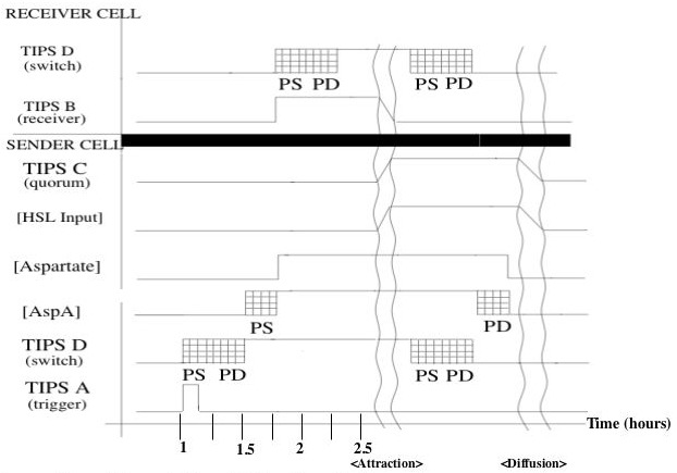
| + | Shown is a putative timing diagram of our system for a typical attractant cycle. At some time the trigger activates randomly, sending a TIPS signal to the switch. The switch output rises with a delay set by protein synthesis and degredation (to be explained in the switch device section). This causes the AspA level to rise with another protein synthesis delay. The corresponding increase in Aspartate will activate the switches of other cells (''receiver cell'' in the diagram). After an undefined attraction period, the cells will have formed a dense enough cluster to activate quorum sensing. The switch will turn off with a similar protein synthesis/degredation delay, and aspartate will begin to diffuse away. The cell cluster will diffuse away, at which point the system will be reset to its initial conditions. | ||
| + | |||
| + | |||
| + | === Population Simulations === | ||
| + | |||
| + | Quicktime movies not yet loaded... | ||
| + | |||
| + | |||
| + | === Characterization === | ||
| + | |||
| + | We have specified various protocols to validate our system part by part. We will validate each individual device in our block diagram separately and then subsequently test compound parts. Our plans for device testing are listed below. | ||
| + | |||
| + | ==== Testing Single Devices ==== | ||
| + | |||
| + | *Trigger | ||
| + | *Switch | ||
| + | *Aspartate Sender | ||
| + | *Aspartate Receiver | ||
| + | *Quorum Sender | ||
| + | *Quorum Receiver | ||
| + | |||
| + | |||
| + | ==== Testing Compound Devices ==== | ||
| + | |||
| + | *Aspartate Sender & Switch | ||
| + | *Aspartate Receiver & Switch | ||
| + | *Quorum Receiver & Switch | ||
| + | |||
| + | ==== Testing Collective Behaviors ==== | ||
| + | *Attractant-Chemotaxis Interaction | ||
| + | *Characterizing Quorum Response to Clustering | ||
| + | |||
| + | |||
| + | === Parts List === | ||
| + | |||
| + | [[Image:Frinkburger.gif]] | ||
| + | |||
| + | {|Systems Device | ||
| + | |Device Name | ||
| + | |Part Description | ||
| + | |BioBricks Number | ||
| + | |- | ||
| + | |} | ||
| + | |||
==IAP 2004 Projects== | ==IAP 2004 Projects== | ||
Descriptions and schematics can be found [http://iap03.igem.org here] | Descriptions and schematics can be found [http://iap03.igem.org here] | ||
Revision as of 00:48, 12 April 2006
Contents |
Overview
During MIT's Independent Activity javascript:insertTags('<math>','</math>','Insert formula here'); Mathematical formula (LaTeX)Period in January 2004, teams designed genetic systems to create cellular patterns varying from bull’s-eyes to polka dots and even dynamic designs where cells swim together. From these designs, standard biological parts were designed and synthesized.
Polkadorks and the E. Coli-brator
est. January 5, 2004
Background
Last year's groups were asked to create systems that blink; this year our job was to create systems that form a spatial design. We, the Polkadorks, chose polkadots for our design and have spent the month of January 2004 working on this system.
Basic Design
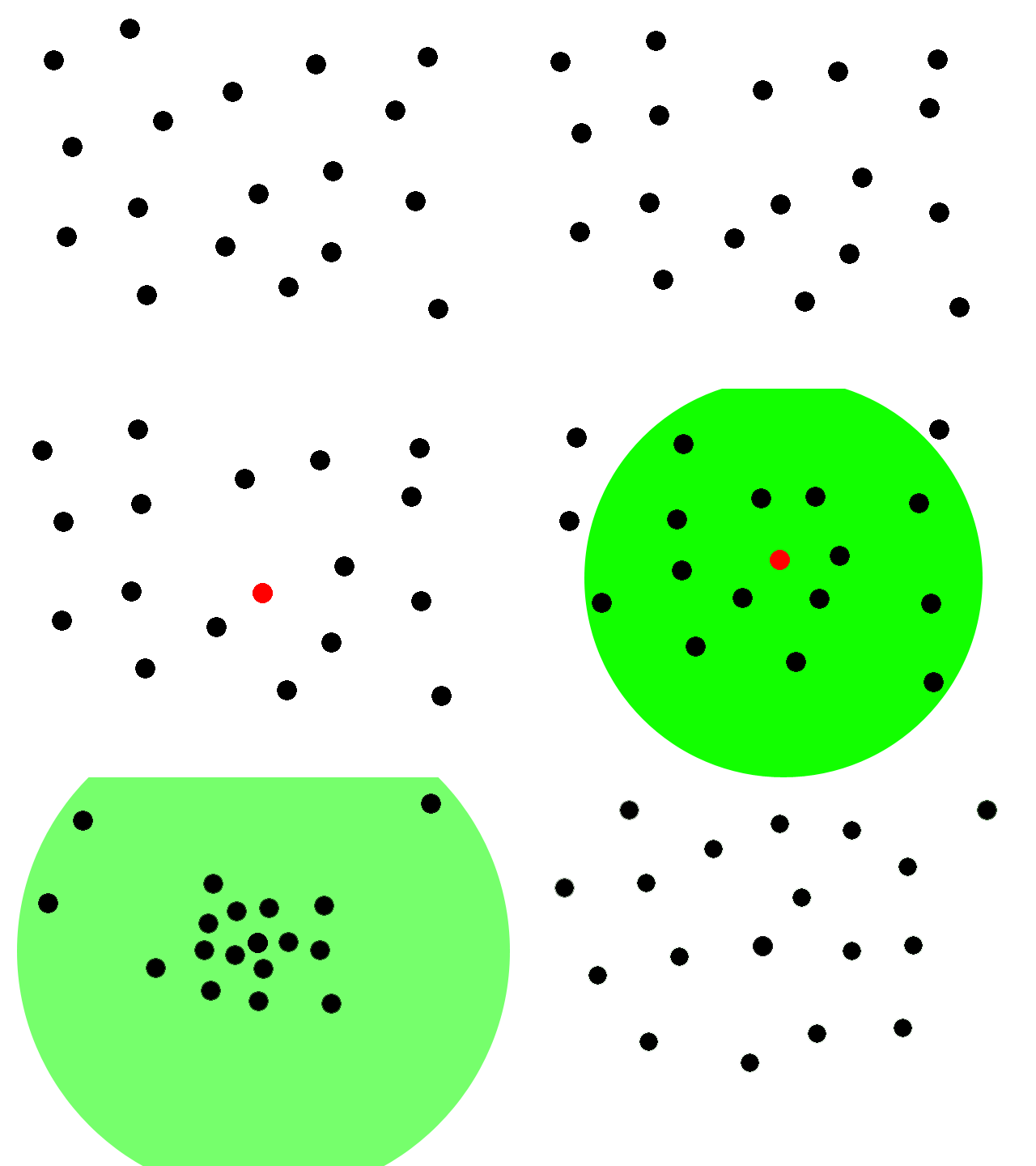
This animation illustrates our basic system. We start with a collection of engineered e-coli moving randomly in plated media. The bacteria are represented by black dots in the animation. Under control of a stochastic element, a few begin excreting an attractant. These bacteria we will call the sender cells. In the movie we have one sender cell represented by the red dot; the green circle represents the attractant diffusing away from the sender cell.
Through chemotaxis, a process by which a cell along a chemical gradient swims toward or away from the stimulus (an attractant in this case), nearby bacteria start swimming towards the sender cells. These bacteria we will call the receiver cells. This way, groups begin forming around the original sender cells on the plate.
All bacteria have been engineered with a quorum sensing mechanism which effectively senses local cell density. In the groups that have formed on our plate, the cell density eventually reaches a certain threshold. The quorum sensing mechanism of the cells then stops secretion of any attractant. The existing attractant then diffuses away. Since there is no more attractant being secreted, the cells will diffuse away and eventually be spread out across the plate once again. Then by the stochastic element a few cells will begin excreting the attractant and the whole process is repeated.
Basically polkadots will form, diffuse, and form again in random areas on the plate. Our system should thus form time-varying patterns based on local random time-varying symmetry breaking.
System Diagram
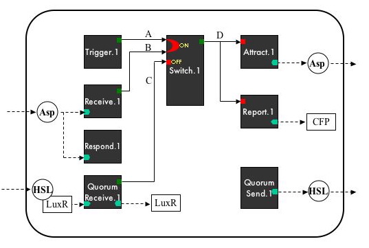
Device Diagram
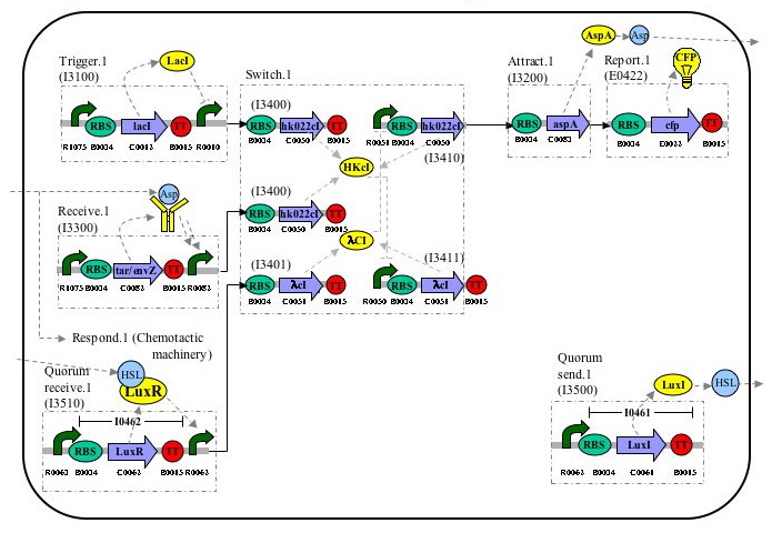
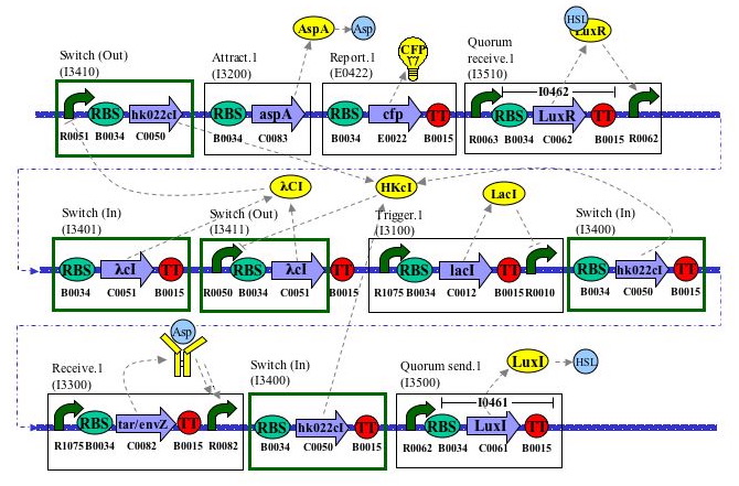
Layout Diagram
Timing Diagram
Shown is a putative timing diagram of our system for a typical attractant cycle. At some time the trigger activates randomly, sending a TIPS signal to the switch. The switch output rises with a delay set by protein synthesis and degredation (to be explained in the switch device section). This causes the AspA level to rise with another protein synthesis delay. The corresponding increase in Aspartate will activate the switches of other cells (receiver cell in the diagram). After an undefined attraction period, the cells will have formed a dense enough cluster to activate quorum sensing. The switch will turn off with a similar protein synthesis/degredation delay, and aspartate will begin to diffuse away. The cell cluster will diffuse away, at which point the system will be reset to its initial conditions.
Population Simulations
Quicktime movies not yet loaded...
Characterization
We have specified various protocols to validate our system part by part. We will validate each individual device in our block diagram separately and then subsequently test compound parts. Our plans for device testing are listed below.
Testing Single Devices
   *Trigger
   *Switch
   *Aspartate Sender
   *Aspartate Receiver
   *Quorum Sender
   *Quorum Receiver
Testing Compound Devices
   *Aspartate Sender & Switch
   *Aspartate Receiver & Switch
   *Quorum Receiver & Switch
Testing Collective Behaviors
   *Attractant-Chemotaxis Interaction
   *Characterizing Quorum Response to Clustering
Parts List
| Device Name | Part Description | BioBricks Number |
IAP 2004 Projects
Descriptions and schematics can be found here

