IAP 2004:Switch
From 2006.igem.org
| Line 1: | Line 1: | ||
__NOTOC__ | __NOTOC__ | ||
| - | + | == Switch == | |
[[Image:IAP 2004 P1-SD2-Switch1.jpg]] | [[Image:IAP 2004 P1-SD2-Switch1.jpg]] | ||
Latest revision as of 14:48, 12 April 2006
Switch
Each of the individual E-Coli making up the Ecolibrator requires an internal element to store its state. We chose to implement this element using Protein DNA Logic (PDL) 'switch'. Each bacterium can either be in a 'high' state in which it tries to attract other bacteria with Aspartate attractant, or in a low quiescent state in which it emits no attractant. This page describes our construction and modeling of the switch in some detail.
Switch Overview
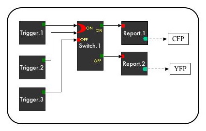
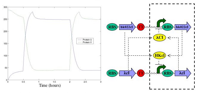
The switch operates on a mutual inhibition principle to achieve bistability. An analagous element exists in digital electronics, and consists of cross coupled NOR gates illustrated in figure (blah). Figure (blah) displays a truth table for the switch. ( Explain inputs) The parts (molecular) level diagram for our switch, in PDL format, is below:
The switch accepts TIPS input and produces TIPS output. The input is in the form The switch consists of four CDS's, two each for \lambda cI and hkcI. Each of these proteins serves to repress the synthesis of the other.
Modeling
As the E-Colibrator is strongly state dependent, we spent a large amout of effort simulating and modeling our switch. We used determinisic network (switchn.m) and kinetic (switchk.m) models (the code is for a Matlab implementation).
Simplified Model The simplified model of our switch is based on the work of (Cantor et al, 2000), and can be written using the following equations:
\frac{du}{dt} = -\frac{u}{\tau} + \frac{\alpha_u}{1+K_vv^2} \frac{dv}{dt} = -\frac{v}{\tau} + \frac{\alpha_v}{1+K_uu^2}
u and v are the protein copy numbers in the cell, which in our case are \lambda cI and hkcI. \tau represents the time constant of decay of the various repressor proteins, which we assume to be 5 minutes given our use of the ssrA tag. \alpha represents the net rate of protein synthesis of each uninhibited promoter, which we take to be 1 protein per second. K is the binding affinity of each repressor protein to its promoter, and is taken to be (something something something).
The following plot illustrates a typical time response of the switch. Predictably the switch has fast rise times on the time scale of \tau, and exihibits bistable values. This model, however, suffers from two main defects. The first is that it is not strongly connected to reality. For example, the parameter \alpha lumps together the already complex processes of translation and transcription into a single constant. This issue becomes more relevant when we consider the second problem--the model's bistability is not very robust. (Gardner et al) analyze the model's robustness and give a bifurcation diagram in their paper. Unfortunately, our repressors operate with a hill coefficient of 2 and possibly a low \alpha.
Show simulation of nullclines, and initial condition plots
The kinetic model is based on a set of kinetic equations that describe the switch in more detail. The kinetic equations were adapted from Ron Weiss' Ph.D thesis (Weiss, 2001). Kinetic parameters assume the repressor proteins are derivatives of phage lambda, with similar kinetics. Actual numerical values are taken from Ptashne (Ptashne, 1982).
It seems more reasonable to change various kinetic parameters in this model to reflect repressor differences. Unfortunately the model's phase space is much larger (12 equations) and its parameter space is of the same order. Thus understanding the effects in this model seems equally difficult. Finally, naively this model does not seem to show robustness in bistabilit, although this issue hasnot been explored in detail.
{show kinetic model output}
Startup
An important issue with the switch concerns how it will start up. Ideally our design would start up with the switch in the off state. We could accomplish this in principle by introducing asymmetry into the switch. There are two obvious ways to do this. The first would be to make the promoters bind their repressors with different affinities. In our system it is doubtful this will happen, operating under the assumption that HKcI and lambda cI and their promoters have similar kinetics. An alternative method, which we pursued, is to use different ribosomal binding sites for synthesizing the repressor proteins.
Devices
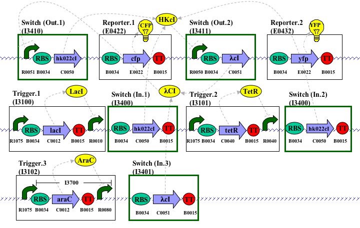
The switch in our system is implemented with two cross-coupled NOR gates. The switch ON input (I3400) produces the Hk022cI repressor, which negatively regulates the switch OFF output promoter (R0050 in I3411). Conversely, the switch OFF input (I3401) produces the Lambda cI repressor, which negatively regulates the switch ON output promoter (R0051 in I3410). Each output state not only produces TIPS, but also produces the protein needed to repress the promoter of the other output state. Therefore, once a switch input determines an output, the output remains stable until a new input toggles the switch.
The hk022cI switch ON output device (I3410) sends TIPS to the attractant sender (I3200) and the CFP reporter (E0422). The lambda cI switch OFF output device (I3411) sends TIPS to a double terminator in E. colibrator designs 1 and 2 (I3000 and I3001) and sends TIPS to an aiiA device in E. colibrator design 3 (I3002) for faster system reset.
Switch In (On) (I3400) The Hk022cI switch input device is duplicated in E. colibrator designs 1 and 3 (I3000 and I3002) in order to accept TIPS from both the Lac trigger (I3100) and the Tar-EnvZ attractant receiver (I3300). In these designs, the duplication of this input device functions as the OR gate within the switch. In design 2, the OR gate is implemented by araC outside of the switch and thus only one instance of this input device occurs.
HkcI protein (C0050) represses the switch OFF output (I3411), which in turn relieves repression of the switch ON output (I3410). Therefore, TIPS into this device lead to TIPS leaving the ON output.
Switch In (Off) (I3401) The lambda cI switch input device accepts TIPS from the quorum receiver (I3510). Lambda cI protein (C0051) represses the switch ON output (I3410), which in turn relieves repression of the switch OFF output (I3411). Therefore, TIPS into this device lead to TIPS leaving the OFF output.
Switch Out (On) (I3410) The hk022cI switch output device is activated when the hk022cI input device (I3400) is on (switch is in the ON state) and is repressed when the lambda cI input device (I3401) is on (switch is in the OFF state). When activated, this output device produces more HkcI protein to maintain the ON state and sends TIPS to the attractant sender (I3200) and the CFP reporter (E0422).
Switch Out (Off) (I3411) The lambda cI switch output device is repressed when the hk022cI input device (I3400) is on (switch is in the ON state) and is activated when the lambda cI input device (I3401) is on (switch is in the OFF state). When activated, this output device produces more Lambda cI protein to maintain the OFF state. In E. colibrator designs 1 and 2 (I3000 and I3001), this device sends TIPS to a double terminator (B0015). In E. colibrator design 3 (I3002), this device sends TIPS to an aiiA device (I0460) to degrade HSL.


