Event Processing Device
From 2006.igem.org
m (→Cloning Steps and Debugging) |
(→References) |
||
| (53 intermediate revisions not shown) | |||
| Line 1: | Line 1: | ||
Back to [[ETH Zurich]] main page. | Back to [[ETH Zurich]] main page. | ||
| + | =Detailed Documentation Of The Event Processing Device (EPD)= | ||
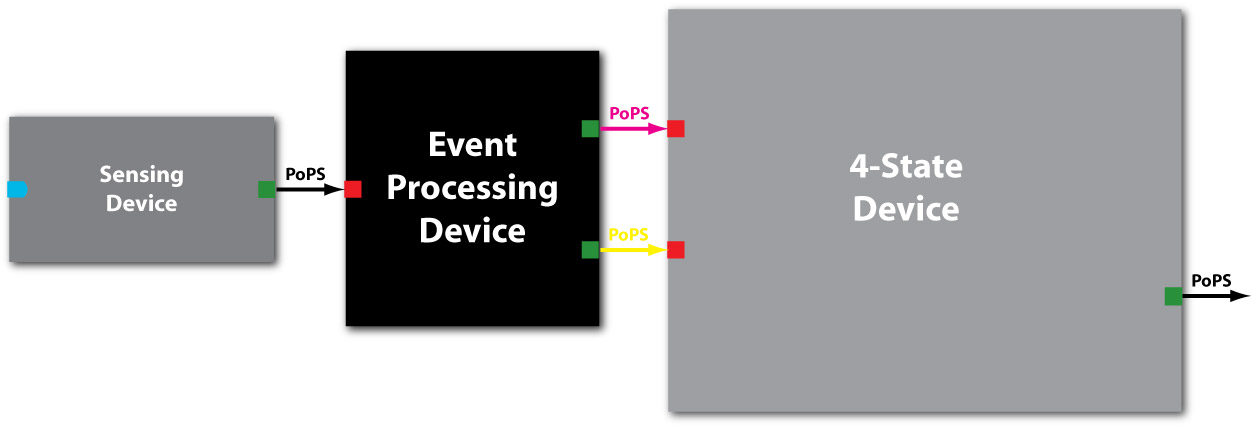
| + | [[image:Sens-EDP-block.jpg|thumb|Figure EPD.1: Schematic of the EPD device as a black box with PoPS as system boundaries between Sensing Device generating the input and the 4SD taking its outputs.]] | ||
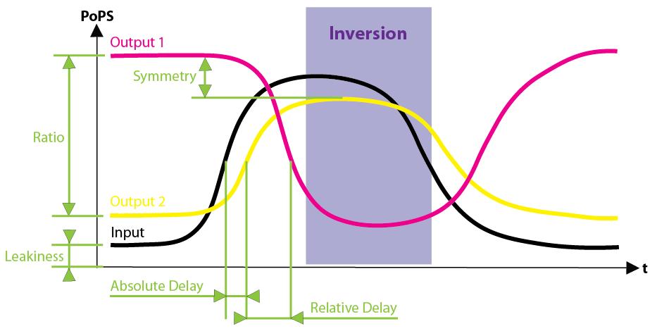
| + | [[image:Qualitative_S-EPD-PrPrm.jpg|thumb|Figure EPD.2: Schematic of the two output signals, output 1 and output 2, in dependence of the input signal (coming from the sensing device, triggered by an external event) in the Event Processing Device]] | ||
| - | = | + | == Purpose == |
| - | + | In a nutshell, the EPD (indicated in black in [Fig EPD.1]) has 2 system boundaries, both of which are characterized by PoPS ('''Po'''lymerase '''P'''er '''S'''econd). Its purpose is to take a single input PoPS and output 2 different PoPS. One of the outputs should be high and the other low when an input (external signal converted to PoPS by the Sensing Device) is high and vice versa when the input is low [Fig EPD.2]. | |
| - | + | ||
| - | == | + | == Basic Functionality == |
| - | + | As indicated on the main page [[ETH Zurich]] we chose to split the overall system into two devices, the [[4-State Device]] and the EPD. Figure EPD.2 shows the basic functionality of the EPD encapsulated in a box with general PoPS interfaces. | |
| - | + | ||
| - | + | ||
| - | + | With this design, any input can be used, as long as a promoter can be found that is either activated or suppressed by this input. At the output, any kind of genes can be added which will be produced depending on the PoPS of that particular input. | |
| - | + | ||
| - | + | ||
| - | + | ||
| - | + | ||
| - | + | ||
| - | + | ||
| - | + | ||
| - | + | ||
| - | + | ||
| - | + | ||
| - | + | ||
| - | + | ||
| - | + | ||
| - | + | ||
| - | + | ||
| - | + | ||
| - | + | ||
| - | + | ||
| - | + | ||
| - | + | ||
| - | + | ||
| - | + | ||
| - | + | ||
| - | + | ||
| - | + | ||
| - | + | ||
| - | + | ||
| - | + | ||
| - | + | ||
| - | + | ||
| - | + | ||
| - | + | ||
| - | + | ||
| - | With this design, any input can be used, as long as a | + | |
| - | + | ||
| - | + | ||
| - | + | ||
| - | + | ||
| - | + | ||
| - | + | ||
| - | + | ||
| - | + | ||
| - | + | ||
| - | + | ||
| - | + | ||
| - | + | ||
| - | + | ||
| - | + | ||
| - | + | ||
| - | + | ||
| - | + | ||
| + | = Design = | ||
==Suitable Strategies== | ==Suitable Strategies== | ||
| - | As shown in the black box above, the core of the device is a regulator sub-module, for which | + | As shown in the black box above, the core of the device is a regulator sub-module, for which different implementation strategies have been investigated. |
We identified various solutions, the remaining ones being | We identified various solutions, the remaining ones being | ||
| - | * The | + | * The λ-phage system with two variants |
** The original anti-parallel version | ** The original anti-parallel version | ||
| - | ** | + | ** Engineered unidirectional versions |
* The Lux-system | * The Lux-system | ||
| - | + | ** The original bidirectional lux cassette of ''Vibrio fischeri'' | |
| + | ** Engineered unidirectional versions | ||
==Selected System== | ==Selected System== | ||
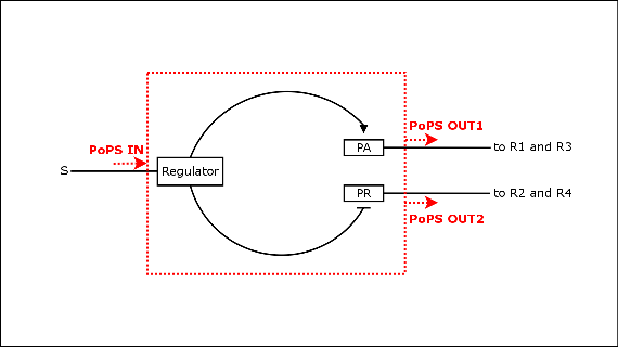
| - | + | [[image:input_device.png|thumb|Figure EPD.3: Schematic of the inner workings of the EPD with regulator protein controlling the two output promoters, as it can be found in the λ-phage system.]] | |
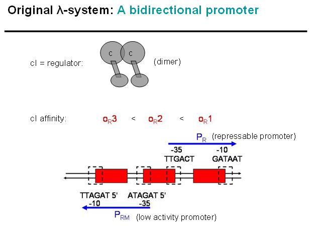
| - | + | [[Image:Lambda-Sys_orig_bidirect.jpg|thumb|Figure EPD.4: Key-points of original bi-directional Lambda-system]] | |
| - | + | [[Image:Lambda-Sys_orig_Pr-repressed.jpg|thumb|Figure EPD.5: Original bi-directional Lambda-system, Pr repressed]] | |
| - | + | [[Image:Lambda-Sys_orig_Prm-repressed.jpg|thumb|Figure EPD.6: Original bi-directional Lambda-system, Prm repressed]] | |
| + | [[Image:Lambda-Sys in INPUT-module.jpg|thumb|Figure EPD.7: Modified Lambda-system in EPD: unidirectional, no OR3]] | ||
| + | Due to limited time, the current availability of parts and the constraints due to the standard restriction sites available in the parts library, we decided to actually implement the unidirectional λ-phage system. As an input we will use IPTG for easy handling and debugging, although the system is of course scalable for other types of inputs. | ||
| - | + | * Advantages of the λ-phage system | |
| - | + | ** Since the two promoters are regulated by the same protein-operator interactions, repression and activation should be symmetrical and have approximately the same delay. | |
| + | ** Parts are available from the registry package '''Registry 7.05'''. | ||
| + | ===Basic Principle of Original λ-phage system=== | ||
| + | We decided to characterize and implement the λ-phage system. The following schematics illustrate the basic concept with the natural λ-phage system (bidirectional), and the planned implementation of the unidirectional version in the EPD [Fig EPD.3]. cI is a dimer and regulates the activity of the two promoter regions, Pr and Prm, on the λ-phage system. Pr is constitutively active and is repressed when cI binds to the two operator regions it overlaps with, OR1 and OR2. Prm is not very active without cI, but has an unknown basal activity. | ||
| - | [ | + | The binding affinity of the operator regions is different, i.e. OR1 > OR2 > OR3, such that cI first binds to OR1, then with cooperativity binds to OR2 [Fig EPD.5]. As soon as cI is bound over the Pr promotor region, Pr will be repressed. However, the presence of cI at OR2 will make it possible for the RNA polymerase to bind to Prm which is then becoming active. |
| - | + | In a third stage [Fig EPD.6], cI also binds to the OR3 region and thus represses Prm again. However, in the modified system, as it can be found in the registry, OR3 has been switched-off through mutation. | |
| + | ===Basic Principle of Modified λ-phage system in EPD=== | ||
| + | Figure EPD.7 illustrates how the modified λ-phage system could be used as a regulator system in the EPD. Here we would not use the original bidirectional system, but the unidirectional one that can be found in the registry, i.e. where Pr and Prm have been separated and OR3 deactivated over mutation. | ||
| - | + | At the input side, we use the LacI-system. The LacI-protein would be present all the time, binding to the Lac-promoter (Plac) and thus blocking it. No cI would normally be produced in this state if the promoter is not leaky. | |
| + | When IPTG is added to the system, it would remove the LacI-protein from the promoter and cI would be produced in this other state. | ||
| - | + | In absence of an input signal (i.e. no IPTG in this debugging system) no cI would be produced, Pr will be constitutively active and Prm would have low basal activity (whose effect will be repressed by the zinc-finger system, see [[4-State Device]]). In a debugging system as shown above, RFP would be produced and indicate this state with red fluorescence. | |
| + | As soon as there is an input signal (i.e. IPTG removing the repressor LacI from the Lac-promoter), cI would be produced, thus repressing Pr and activating Prm (figure EPD.6). RFP would be produced and GFP production would cease. Thus, the green fluorescence would change to red fluorescence, if everything works as planned. | ||
| - | [ | + | = Actual Implementation = |
| + | ==Parts and Methods== | ||
| + | The current status is that we will be able to clone the whole EPD and its intermediate steps for debugging purposes over [http://parts2.mit.edu/r/parts/htdocs/Assembly/index.cgi standard assembly] with parts found in the package '''Registry 7.05'''. | ||
| - | + | ==Full Sequence== | |
| + | [[Image:EPDanimation-pure.jpg|thumb|Figure EPD.8: List of parts from the Registry 7.05 that constitute the Event Processing Device.]] | ||
| + | Figure EPD.8 illustrates the full sequence of the planned Sensing Device and the EPD. tetR is a constitutive promoter, thus lacI is continuously produced and repressing the lacI promoter. Note that the Pr and Prm parts are separated (unidirectional, not bidirectional) and that the Prm+ part from the library is with a modified (non-functional) OR3 region. Also, for the cI part we are using both the normal one, P0451, and the one with an additional degradation tag, P0455. | ||
| + | ==Assembly== | ||
| + | A single cloning session will typically take 4 days (miniprep - digestion - ligation - transformation - clones check), if carried out by an experienced person and if no mistake is made. We assumed that one week per cloning step would be more realistic. It looks like we have 3 cloning sessions with each 1 week for the EPD alone, which makes 3 weeks. However, as expected we encountered several problems in the lab and had to repeat many steps. The essential parts for first test of the EPD are ready now, however, Giorgia, Hervé, and Martje are still cloning certain parts for testing and debugging and we are planning additional ones. | ||
| - | + | [[Image:Cloning-steps.input-module.gif|thumb|Figure EPD.8: Planned cloning steps and current status (image updated according to results).]] | |
| - | + | Figure EPD.8 illustrates how we plan to clone the EPD and the current status of this work (green: success/available): | |
| - | + | ||
| - | + | ||
| - | + | ||
| - | + | ||
| - | + | ||
| - | + | ||
| - | + | ||
| - | + | ||
| - | + | ||
| - | + | ||
| - | + | ||
| - | + | ||
| - | + | ||
| - | + | ||
| - | + | ||
| - | + | ||
| - | + | ||
| - | + | ||
| - | + | ||
| - | + | ||
| - | + | ||
| - | + | ||
| - | + | ||
| - | + | ||
| - | + | ||
| - | + | ||
| - | + | ||
| - | + | ||
| - | + | ||
| - | + | ||
| - | + | ||
| - | + | ||
| - | + | ||
* The number in the boxes correspond to the part number in the [http://parts.edu.mit registry]. | * The number in the boxes correspond to the part number in the [http://parts.edu.mit registry]. | ||
* The yellow and orange parts are the intermediate combinations we will get as a result of cloning components together. These we will add to the registry. | * The yellow and orange parts are the intermediate combinations we will get as a result of cloning components together. These we will add to the registry. | ||
* The orange parts are for debugging/testing purposes only. Note that we might chose to skip certain testing steps due to time constraints. | * The orange parts are for debugging/testing purposes only. Note that we might chose to skip certain testing steps due to time constraints. | ||
| - | * | + | * Green indicates success/availability. Thus in the end all yellow and orange parts should be replaced by green parts. |
* The individual cloning steps are indicated by the symbol for a logical AND (arrow up in grey circle). When only the more suitable part has to be chosen to continue, a logical OR indicates that (arrow down in grey circle). The part to the right of the logical AND is attached downstream to the left part. | * The individual cloning steps are indicated by the symbol for a logical AND (arrow up in grey circle). When only the more suitable part has to be chosen to continue, a logical OR indicates that (arrow down in grey circle). The part to the right of the logical AND is attached downstream to the left part. | ||
| + | * The Zinc Hand parts with operator regions, here indicated by ''RX System A/B'', developed by the group working on the [[4-State Device]] are indicated in bright pink. These systems will be synthesized by Blue Heron - unfortunately it seems that they are incredibly behind schedule and that they cannot deliver before the jamboree. | ||
| + | * For the final and complete COUNTER-System will we will need to clone the Pr/Prm promoters at the beginning of each of the Zinc Hand systems (Prm for R1 and R3, Pr for R2 and R4) and add the selected EPD sequence (either composite part J05500 or J05501 - whichever is better, but most likely J05501) in front of everything. The final COUNTER-System will thus consist of 5 intermediate parts (here in the graph labeled as the chosen composite X plus the 4 Zinc Hand systems with the corresponding promoter, Pr or Prm, in front). It will take another 1 or 2 sessions to clone those components all together to a single system, depending on whether we want to put it on a single plasmid. | ||
| + | * There are 2 cloning sessions (indicated by light green horizontal bars) for the crucial parts of the EPD. | ||
| + | * There are many more cloning sessions, 3-n, to clone intermediates for [[Event Processing Device#Tests and Characterization | tests and characterization]]. | ||
* The purpose of certain results, i.e. the testing, is commented in square boxes around the resulting part(s). | * The purpose of certain results, i.e. the testing, is commented in square boxes around the resulting part(s). | ||
| - | |||
| - | |||
| - | |||
| - | |||
| - | |||
| - | |||
| - | |||
| - | |||
| - | |||
| - | |||
| - | |||
| - | |||
| - | |||
| - | |||
| - | |||
| - | |||
| + | == Tests and Characterization == | ||
| + | We have ongoing experiments and the documentation is not up to date / well structured. In the meantime, please refer to the [[Experiments]] page. | ||
Back to [[ETH Zurich]] main page. | Back to [[ETH Zurich]] main page. | ||
Latest revision as of 19:39, 5 November 2005
Back to ETH Zurich main page.
Contents |
Detailed Documentation Of The Event Processing Device (EPD)
Purpose
In a nutshell, the EPD (indicated in black in [Fig EPD.1]) has 2 system boundaries, both of which are characterized by PoPS (Polymerase Per Second). Its purpose is to take a single input PoPS and output 2 different PoPS. One of the outputs should be high and the other low when an input (external signal converted to PoPS by the Sensing Device) is high and vice versa when the input is low [Fig EPD.2].
Basic Functionality
As indicated on the main page ETH Zurich we chose to split the overall system into two devices, the 4-State Device and the EPD. Figure EPD.2 shows the basic functionality of the EPD encapsulated in a box with general PoPS interfaces.
With this design, any input can be used, as long as a promoter can be found that is either activated or suppressed by this input. At the output, any kind of genes can be added which will be produced depending on the PoPS of that particular input.
Design
Suitable Strategies
As shown in the black box above, the core of the device is a regulator sub-module, for which different implementation strategies have been investigated.
We identified various solutions, the remaining ones being
- The λ-phage system with two variants
- The original anti-parallel version
- Engineered unidirectional versions
- The Lux-system
- The original bidirectional lux cassette of Vibrio fischeri
- Engineered unidirectional versions
Selected System
Due to limited time, the current availability of parts and the constraints due to the standard restriction sites available in the parts library, we decided to actually implement the unidirectional λ-phage system. As an input we will use IPTG for easy handling and debugging, although the system is of course scalable for other types of inputs.
- Advantages of the λ-phage system
- Since the two promoters are regulated by the same protein-operator interactions, repression and activation should be symmetrical and have approximately the same delay.
- Parts are available from the registry package Registry 7.05.
Basic Principle of Original λ-phage system
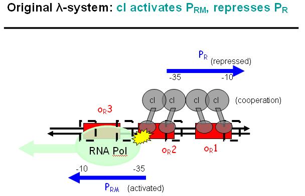
We decided to characterize and implement the λ-phage system. The following schematics illustrate the basic concept with the natural λ-phage system (bidirectional), and the planned implementation of the unidirectional version in the EPD [Fig EPD.3]. cI is a dimer and regulates the activity of the two promoter regions, Pr and Prm, on the λ-phage system. Pr is constitutively active and is repressed when cI binds to the two operator regions it overlaps with, OR1 and OR2. Prm is not very active without cI, but has an unknown basal activity.
The binding affinity of the operator regions is different, i.e. OR1 > OR2 > OR3, such that cI first binds to OR1, then with cooperativity binds to OR2 [Fig EPD.5]. As soon as cI is bound over the Pr promotor region, Pr will be repressed. However, the presence of cI at OR2 will make it possible for the RNA polymerase to bind to Prm which is then becoming active.
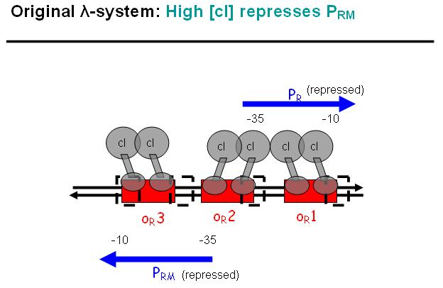
In a third stage [Fig EPD.6], cI also binds to the OR3 region and thus represses Prm again. However, in the modified system, as it can be found in the registry, OR3 has been switched-off through mutation.
Basic Principle of Modified λ-phage system in EPD
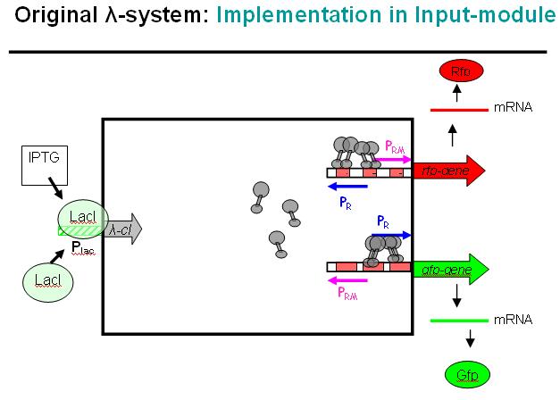
Figure EPD.7 illustrates how the modified λ-phage system could be used as a regulator system in the EPD. Here we would not use the original bidirectional system, but the unidirectional one that can be found in the registry, i.e. where Pr and Prm have been separated and OR3 deactivated over mutation.
At the input side, we use the LacI-system. The LacI-protein would be present all the time, binding to the Lac-promoter (Plac) and thus blocking it. No cI would normally be produced in this state if the promoter is not leaky. When IPTG is added to the system, it would remove the LacI-protein from the promoter and cI would be produced in this other state.
In absence of an input signal (i.e. no IPTG in this debugging system) no cI would be produced, Pr will be constitutively active and Prm would have low basal activity (whose effect will be repressed by the zinc-finger system, see 4-State Device). In a debugging system as shown above, RFP would be produced and indicate this state with red fluorescence.
As soon as there is an input signal (i.e. IPTG removing the repressor LacI from the Lac-promoter), cI would be produced, thus repressing Pr and activating Prm (figure EPD.6). RFP would be produced and GFP production would cease. Thus, the green fluorescence would change to red fluorescence, if everything works as planned.
Actual Implementation
Parts and Methods
The current status is that we will be able to clone the whole EPD and its intermediate steps for debugging purposes over [http://parts2.mit.edu/r/parts/htdocs/Assembly/index.cgi standard assembly] with parts found in the package Registry 7.05.
Full Sequence
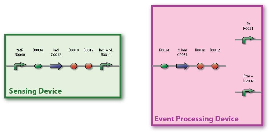
Figure EPD.8 illustrates the full sequence of the planned Sensing Device and the EPD. tetR is a constitutive promoter, thus lacI is continuously produced and repressing the lacI promoter. Note that the Pr and Prm parts are separated (unidirectional, not bidirectional) and that the Prm+ part from the library is with a modified (non-functional) OR3 region. Also, for the cI part we are using both the normal one, P0451, and the one with an additional degradation tag, P0455.
Assembly
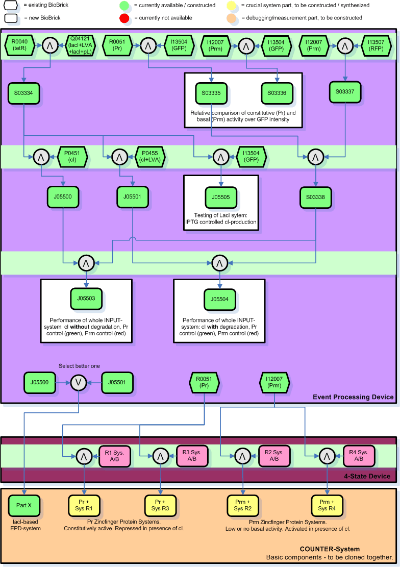
A single cloning session will typically take 4 days (miniprep - digestion - ligation - transformation - clones check), if carried out by an experienced person and if no mistake is made. We assumed that one week per cloning step would be more realistic. It looks like we have 3 cloning sessions with each 1 week for the EPD alone, which makes 3 weeks. However, as expected we encountered several problems in the lab and had to repeat many steps. The essential parts for first test of the EPD are ready now, however, Giorgia, Hervé, and Martje are still cloning certain parts for testing and debugging and we are planning additional ones.
Figure EPD.8 illustrates how we plan to clone the EPD and the current status of this work (green: success/available):
- The number in the boxes correspond to the part number in the [http://parts.edu.mit registry].
- The yellow and orange parts are the intermediate combinations we will get as a result of cloning components together. These we will add to the registry.
- The orange parts are for debugging/testing purposes only. Note that we might chose to skip certain testing steps due to time constraints.
- Green indicates success/availability. Thus in the end all yellow and orange parts should be replaced by green parts.
- The individual cloning steps are indicated by the symbol for a logical AND (arrow up in grey circle). When only the more suitable part has to be chosen to continue, a logical OR indicates that (arrow down in grey circle). The part to the right of the logical AND is attached downstream to the left part.
- The Zinc Hand parts with operator regions, here indicated by RX System A/B, developed by the group working on the 4-State Device are indicated in bright pink. These systems will be synthesized by Blue Heron - unfortunately it seems that they are incredibly behind schedule and that they cannot deliver before the jamboree.
- For the final and complete COUNTER-System will we will need to clone the Pr/Prm promoters at the beginning of each of the Zinc Hand systems (Prm for R1 and R3, Pr for R2 and R4) and add the selected EPD sequence (either composite part J05500 or J05501 - whichever is better, but most likely J05501) in front of everything. The final COUNTER-System will thus consist of 5 intermediate parts (here in the graph labeled as the chosen composite X plus the 4 Zinc Hand systems with the corresponding promoter, Pr or Prm, in front). It will take another 1 or 2 sessions to clone those components all together to a single system, depending on whether we want to put it on a single plasmid.
- There are 2 cloning sessions (indicated by light green horizontal bars) for the crucial parts of the EPD.
- There are many more cloning sessions, 3-n, to clone intermediates for tests and characterization.
- The purpose of certain results, i.e. the testing, is commented in square boxes around the resulting part(s).
Tests and Characterization
We have ongoing experiments and the documentation is not up to date / well structured. In the meantime, please refer to the Experiments page.
Back to ETH Zurich main page.
