4-State Device
From 2006.igem.org
(Added tables) |
(→4-State Device parts diagram: pic update) |
||
| (8 intermediate revisions not shown) | |||
| Line 16: | Line 16: | ||
== Selected System == | == Selected System == | ||
| - | Considering the modularity as the first criterion for the selection of the system, we considered that the Zinc Finger Protein approach would be | + | Considering the modularity as the first criterion for the selection of the system, we considered that the Zinc Finger Protein (ZFP) approach would be optimal. Indeed, the operators could be as short as 9 nucleotide long and the specificity can be easily increased by either increasing the number of fingers in the ZFP or by coupling ZFP together via Leucine Zippers. |
The recognition sequence can then be scaled up to 18 nucleotides or even further. | The recognition sequence can then be scaled up to 18 nucleotides or even further. | ||
Known repressors such as tetR remain a possibility for our system because of the tunability that this repressor-operator can offer (via tetracycline for the TetR-TetO couple). | Known repressors such as tetR remain a possibility for our system because of the tunability that this repressor-operator can offer (via tetracycline for the TetR-TetO couple). | ||
| + | |||
The silencing approach has been dropped because of the lack of modularity and the difficulty to achieve full repression via silencing approaches in bacteria. | The silencing approach has been dropped because of the lack of modularity and the difficulty to achieve full repression via silencing approaches in bacteria. | ||
| - | + | The selected approach (ZFP) allowed us to put the binding sites for the repressors directly after start of transcription and before the ribosome binding site to prevent RNA polymerase to transcribe the gene. This design allows us to put any promoter in front of the binding site. This option gives a very high degree of modularity. | |
| - | + | When we decide to scale up the number of counters in order to count n^2, we need to design 4 new repressors for each 4 state device. With the Zinc Finger Protein approach we can easily design new sequence specific repressors based on the ZFP - DNA recognition motif database available. | |
= Actual Implementation = | = Actual Implementation = | ||
| Line 34: | Line 35: | ||
The 4-State Device uses two inputs to sequentially switch through its four states. Note that this behavior can be observed abstractly in the concept section. | The 4-State Device uses two inputs to sequentially switch through its four states. Note that this behavior can be observed abstractly in the concept section. | ||
| - | To achieve such behavior in our system, we use four interconnected gates. In the following, we call them ''NOR gates''. Each of our NOR gates has three inputs. All of them have to be low for the output to be high. | + | To achieve such behavior in our system, we use four interconnected gates. In the following, we call them ''NOR gates''. Each of our NOR gates has three inputs. All of them have to be low for the output to be high. In boolean logic, this reads as out=(NOT_in_1 ^ NOT_in_2 ^ ... ^ NOT_in_n) <b>(i can't figure out how this f*****' math mode works! Can someone more savvy put this in math mode?, jonas</b> |
===== Electrical NOR gate ===== | ===== Electrical NOR gate ===== | ||
| Line 43: | Line 44: | ||
===== Biological NOR gate ===== | ===== Biological NOR gate ===== | ||
Biologically, a NOR gate can be implemented through a promoter with high basal activity that is repressed by three effectors. If there is at least one of the three repressors, transcription is inhibited. | Biologically, a NOR gate can be implemented through a promoter with high basal activity that is repressed by three effectors. If there is at least one of the three repressors, transcription is inhibited. | ||
| - | Each NOR | + | Each NOR gate expresses a repressor protein. (Note that such a biological NOR gate has no POPs interfaces) |
| - | [[Image: | + | [[Image:NOR.gif]] |
===== 4-State Device circuit diagram ===== | ===== 4-State Device circuit diagram ===== | ||
| Line 53: | Line 54: | ||
===== 4-State Device parts diagram ===== | ===== 4-State Device parts diagram ===== | ||
| - | [[Image: | + | [[Image:4StateDevice.png]] |
In the design of the Event Processing Device, input 1 and input 2 have opposite activity, meaning that either R1/R3 or R2/R4 is active. Furthermore, since R1 and R3 (respectively R2 and R4) are repressing each other, only one of the two is active. Therefore, in a stable situation, only 1 of the 4 repressor proteins is expressed. | In the design of the Event Processing Device, input 1 and input 2 have opposite activity, meaning that either R1/R3 or R2/R4 is active. Furthermore, since R1 and R3 (respectively R2 and R4) are repressing each other, only one of the two is active. Therefore, in a stable situation, only 1 of the 4 repressor proteins is expressed. | ||
| Line 74: | Line 75: | ||
ERF repressor domain. a repressor domain in eukaryotes. | ERF repressor domain. a repressor domain in eukaryotes. | ||
| - | -''LZ'' | + | - ''LZ'' |
Leucine zipper. For dimerization. | Leucine zipper. For dimerization. | ||
| Line 154: | Line 155: | ||
binding of ZFP. describe choice of binding sites. Describe the function of RNA pol II. emphasize: modularity! | binding of ZFP. describe choice of binding sites. Describe the function of RNA pol II. emphasize: modularity! | ||
| - | Another important aspect is the overall goal of keeping the design modular - one of the most important aspects of | + | Another important aspect is the overall goal of keeping the design modular - one of the most important aspects of this contest. |
Latest revision as of 19:58, 5 November 2005
Back to the ETH Zurich main page.
Contents |
Purpose
The 4-State Device (4SD) uses two inputs to sequentially switch through its four states. The four states are used to keep track of changes of the inputs. One state is connected to the output.
Design
Suitable Strategies
For realizing the design we need one repressor for each state. For this purpose there are several possibilities that can be considered:
- Silencing approach (antisense RNAs, short hairpin RNAs (shRNAs)) to reduce the pool of translatable mRNAs
- Existing Repressor-Operator (for example TetR-TetO)
- Designing new repressors (for example Zinc Finger Proteins)
Selected System
Considering the modularity as the first criterion for the selection of the system, we considered that the Zinc Finger Protein (ZFP) approach would be optimal. Indeed, the operators could be as short as 9 nucleotide long and the specificity can be easily increased by either increasing the number of fingers in the ZFP or by coupling ZFP together via Leucine Zippers. The recognition sequence can then be scaled up to 18 nucleotides or even further.
Known repressors such as tetR remain a possibility for our system because of the tunability that this repressor-operator can offer (via tetracycline for the TetR-TetO couple).
The silencing approach has been dropped because of the lack of modularity and the difficulty to achieve full repression via silencing approaches in bacteria.
The selected approach (ZFP) allowed us to put the binding sites for the repressors directly after start of transcription and before the ribosome binding site to prevent RNA polymerase to transcribe the gene. This design allows us to put any promoter in front of the binding site. This option gives a very high degree of modularity.
When we decide to scale up the number of counters in order to count n^2, we need to design 4 new repressors for each 4 state device. With the Zinc Finger Protein approach we can easily design new sequence specific repressors based on the ZFP - DNA recognition motif database available.
Actual Implementation
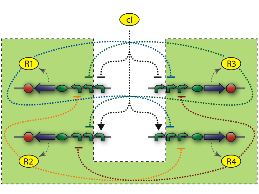
The central part of the counter is the 4SD. When input changes the next state is reached and the repressor is expressed. Every Repressor represses all other states except for the next. For example R1 represses R3 and R4, but not R2. This forces a progression of states R1 to R4 during the cycles of the input.
In the figure below is a parts-view of the device with PoPS interfaces (i/o).
Basic Functionality
The 4-State Device uses two inputs to sequentially switch through its four states. Note that this behavior can be observed abstractly in the concept section.
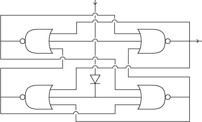
To achieve such behavior in our system, we use four interconnected gates. In the following, we call them NOR gates. Each of our NOR gates has three inputs. All of them have to be low for the output to be high. In boolean logic, this reads as out=(NOT_in_1 ^ NOT_in_2 ^ ... ^ NOT_in_n) (i can't figure out how this f*****' math mode works! Can someone more savvy put this in math mode?, jonas
Electrical NOR gate
A NOR gate is a very common part in electrical engineering.
Biological NOR gate
Biologically, a NOR gate can be implemented through a promoter with high basal activity that is repressed by three effectors. If there is at least one of the three repressors, transcription is inhibited. Each NOR gate expresses a repressor protein. (Note that such a biological NOR gate has no POPs interfaces)
4-State Device circuit diagram
4-State Device parts diagram
In the design of the Event Processing Device, input 1 and input 2 have opposite activity, meaning that either R1/R3 or R2/R4 is active. Furthermore, since R1 and R3 (respectively R2 and R4) are repressing each other, only one of the two is active. Therefore, in a stable situation, only 1 of the 4 repressor proteins is expressed.
Let us assume that R1 is being expressed. Input 2 must then be low, and therefore input 1 high. This situation is stable and remains until there is a change in the inputs. Now, if input 1 decreases, and input 2 increases, the expression of R1 will come to a halt. Since input 1 is now low, either R2 or R4 will be expressed. At this stage, R1 is still present in relatively high concentration and by repressing R4, it tips the balance in favor of R2, leading to a new stable state in which only R2 is expressed.
Note that electrical engineers call such a device a "J-K flip flop". It can also be seen as a combination of two toggle switches (Atkinson03), each being able to store one bit.
Biological Details
In the design of the repressor protein we use the following domains:
- Zinc Finger (ZF) DNA binding domain
- NTD The N-terminal polymerase domain from NusA. This protein has a RNA polymerase halting properties.
- ERD ERF repressor domain. a repressor domain in eukaryotes.
- LZ Leucine zipper. For dimerization.
If it turns out that repression has been used in all the literature we can find, then we would be better off to play safe and include them:
- Beerli PNAS 1998: they fused ZF to KRAB repressor and it has a stronger effect compare to ZF alone (see p14632 graph A)
- Beerli Nat Biotech review feb2002 : if you read the complete paragraph on gene repression (p 132), it gives strong evidence that we should fuse the ZF to a repressor (apparently at the N-Term of the ZF)
It is stated that polymerase blockade through ZF only is not very efficient. We can not be sure that the 45 amino acid long KRAB domain will work, if it doesn't exist in prokaryotes. KRAB domains have a very specific interaction with a co-repressor molecule. It might be better to find something already known to work in bacteria or skip the repressor approach altogether.
The different designs of repressors
| BioBrick Part | Number of ZF domains | LZ domain | TF domain |
|---|---|---|---|
| BBa_J05101 | 3 | - | - |
| BBa_J05108 | 3* | CREBH | - |
| BBa_J05109 | 3* | ATF6 | - |
| BBa_J05110 | 3* | YAP7 | - |
| BBa_J05111 | 3* | cMaf | - |
| BBa_J05112 | 3 | - | ERD |
| BBa_J05113 | 3* | ATF6 | KRAB |
| BBa_J05114 | 3* | ATF6 | NTD |
| BBa_J05115 | 6 | - | - |
BioBrick parts
| State | Repressor | Regulator | Comments |
|---|---|---|---|
| R1 | BBa_J05311 | BBa_J05215 | |
| R3 | BBa_J05312 | BBa_J05216 | |
| R2 | BBa_J05313 | BBa_J05217 | |
| R4 | BBa_J05314 | BBa_J05218 |
| Nickname | Length | SacI | KpnI | NheI | EcoRI | XbaI | SpeI | PstI |
|---|---|---|---|---|---|---|---|---|
| BBa_J05215+BBa_J05108 | 603 | 1 | 91 | 598 | 7, 97 | 22, 112 | 71, 578 | 85, 592 |
| BBa_J05216+BBa_J05109 | 582 | 1 | 91 | 577 | 7, 97 | 22, 112 | 71, 557 | 85, 571 |
| BBa_J05217+BBa_J05110 | 609 | 1 | 91 | 604 | 7, 97 | 22, 112 | 71, 584 | 85, 598 |
| BBa_J05218+BBa_J05111 | 600 | 1 | 91 | 595 | 7, 97 | 22, 112 | 71, 575 | 85, 589 |
| BBa_J05221+BBa_J05101 | 498 | 1 | 112 | 493 | 7, 118 | 22, 133 | 92, 473 | 106, 487 |
| BBa_J05114 | 854 | 1 | 849 | - | 7 | 22 | 829 | 843 |
| BBa_J05112 | 524 | 1 | 519 | - | 7 | 22 | 499 | 513 |
| BBa_J05222+BBa_J05115 | 676 | 1 | 87 | 671 | 7, 93 | 22, 108 | 67, 651 | 81, 665 |
The provider of the synthesized DNA used for the zinc fingerers has a lower cost limit of $500. To reduce cost per base pair for short sequences we put the short sequences together with a long sequence with restriction sites between them. the trick we use to reduce cost, by having an extra step of cloning.
binding of ZFP. describe choice of binding sites. Describe the function of RNA pol II. emphasize: modularity! Another important aspect is the overall goal of keeping the design modular - one of the most important aspects of this contest.
We have two alternatives for placing the binding sites.
1. Binding sites in the promoter. This would prevent the polymerase from binding to the promotor. Although this might be most likely to work, we have chosen to not pursue this alternative, while we are quite intrigued by the possibility of a roadblock. The operator regions (i.e. the "roadblocks" that will prevent of the RNApolymerase to transcribe the gene) form a BioBrick that should be inserted between the promoter region and the ribosome binding site in order to keep the design modular.
2. Binding sites directly after the start of transcription and before the ribosome binding site. This alternative is attractive, since it would allow for a high degree of modularity. In theory the ZFP would act as an extra "roadblock-operator" and any promotor could be used in front of the protein.
The ZFP roadblock operator regions (from now on referred to as: operators) consists of binding motifs for two repressors. The two binding motifs are usually spaced with 5 base pairs (gcgcg). Some data of the binding strength were available and we have chosen operators with the affinity estimated to K_d = 3-40 nM.
| Part | Binding Site Seq | est Kd [nM] | # exact matches | Hamming Dist 1 | Hamming Dist 2 | Hamming Dist 3 |
|---|---|---|---|---|---|---|
| BBa_J05100 | ggaggggac | 4 | 5 | 267 | 6196 | 65733 |
| BBa_J05102 | ggaggcggg | 30 | 17 | 799 | 12589 | 95996 |
| BBa_J05101 | gggggcgag | 3 | 15 | 634 | 10173 | 82956 |
| BBa_J05103 | ggggccgga | 45 | 44 | 848 | 11317 | 91422 |
| BBa_J05108 | gtcccctccggaggggac | N/A | 0 | 0 | 0 | 1 |
| BBa_J05109 | ctcgcccccgggggcgag | N/A | 0 | 0 | 0 | 2 |
| BBa_J05110 | cccgcctccggaggcggg | N/A | 0 | 0 | 0 | 4 |
| BBa_J05111 | tccggccccggggccgga | N/A | 0 | 0 | 0 | 6 |
| BBa_J05115 | gggggcgaggggggcgag | N/A | 0 | 0 | 0 | 3 |
Degradation rates????
Tests: design all tests. To test whether our assumptions about using multiple zinc finger proteins (ZFP) as repressors (i.e. roadblocks) will actually work, we will build a tester/debugging device in parallel with the counter.
| Repressor | Regulator | Comments |
|---|---|---|
| BBa_J05112 R3-e2+ERD | Regulator for R3-ATF6 | |
| BBa_J05113 R3-ATF6+ NTD | BBa_J05221 Triple Binding Site for R3-ATF6 | |
| BBa_J05114 R3-ATF6+NTD | Regulator for R3-ATF6 | |
| BBa_J05101 R3-e2 | Regulator for R3-ATF6 | |
| BBa_J05115 ZF-2*e2 | ZF-2*e2 Binding Site |
4SD system
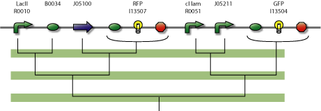
The 4SD system consists of 4 proteins with 4 operator regions. It has an interface boundary with input module (Pr and Prm). Repressor R3 is connected to a reporter to be able to count to modulo two.
assembly diagram of device.


