Introduction
From 2006.igem.org
(→breakdown into modules) |
|||
| Line 48: | Line 48: | ||
=breakdown into modules= | =breakdown into modules= | ||
| + | The counter can be partitiond into two (fairly) independent devices: | ||
| + | * Input Module | ||
| + | * NOR Module | ||
| + | |||
| + | Both are designed as PoPS input - PoPS output devices (as specified in the MIT nomenclature) | ||
| + | |||
| + | == Input Module == | ||
| + | In this device, we want to capsule the path from S to the R's: | ||
| + | [[Image:counter_layered_input_box.png]] | ||
| + | |||
| + | |||
| + | If we leave away the parts that don't belong to the Input Module, we are left with | ||
| + | [[Image:counter_layered_input_box_only.png]] | ||
| + | |||
| + | |||
| + | As an abstract model the Input device looks as follows: | ||
| + | [[Image:input_device.png]] | ||
| + | |||
| + | One of the outputs (PoPS OUT1) should be high and the other (PoPS OUT2) low when the PoPS IN is high and vice versa when PoPS IN is low. | ||
| + | |||
| + | |||
| + | |||
| + | == NOR Module == | ||
Revision as of 09:27, 4 October 2005
Contents |
The step-by-step procedure
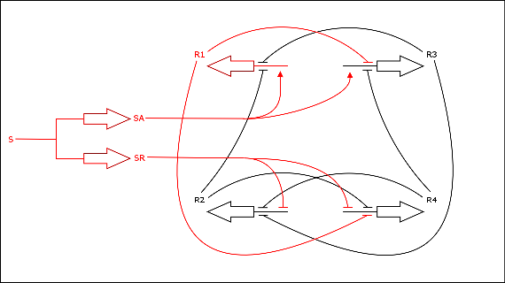
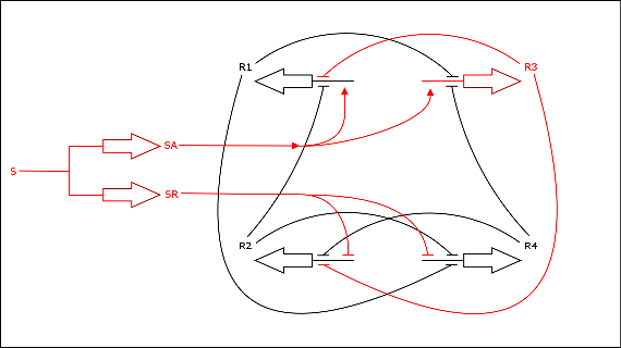
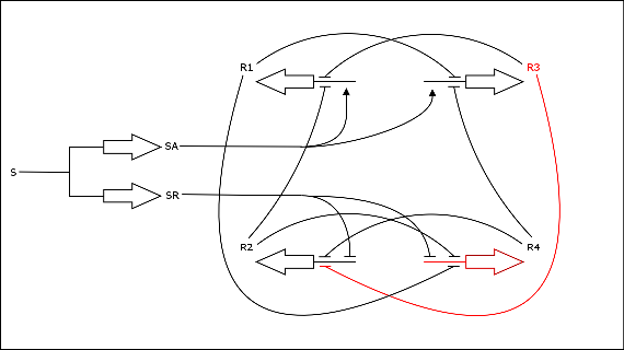
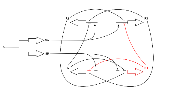
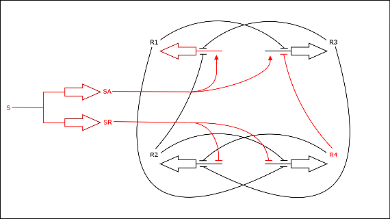
Here you can find a detailed description of the state transitions that occur in the counter. The counter has four states, R1 to R4.
- start state
S is active, R1 is active
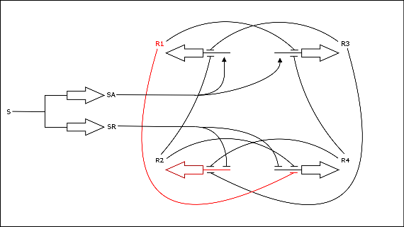
- transition to state R2
S is deactivated, R1 is still present (but fading) and represses R4. R2 gets produced
- state R2
S is inactive, R2 is active
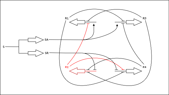
- transition to state R3
S is activated, R2 is still present (but fading) and represses R1. R3 gets produced
- state R3
S is active, R3 is active
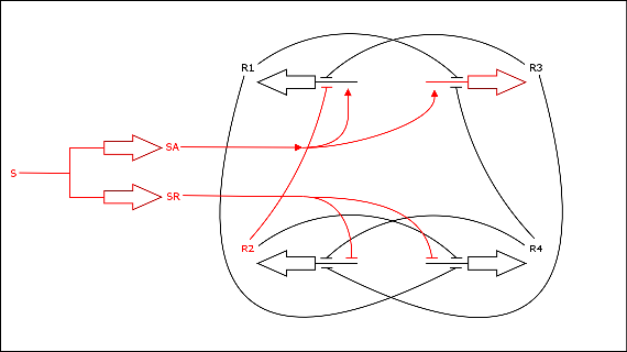
- transition to state R4
S is deactivated, R3 is still present (but fading) and represses R2. R4 gets produced
- state R4
S is inactive, R4 is active
- transition to state R1 (start state)
S is activated, R4 is still present (but fading) and represses R3. R1 gets produced
- ...and we return to the start state
S is active, R1 is active
breakdown into modules
The counter can be partitiond into two (fairly) independent devices:
- Input Module
- NOR Module
Both are designed as PoPS input - PoPS output devices (as specified in the MIT nomenclature)
Input Module
In this device, we want to capsule the path from S to the R's:
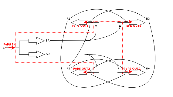
If we leave away the parts that don't belong to the Input Module, we are left with
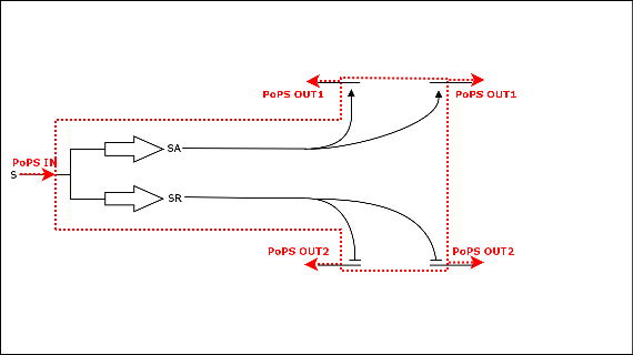
As an abstract model the Input device looks as follows:
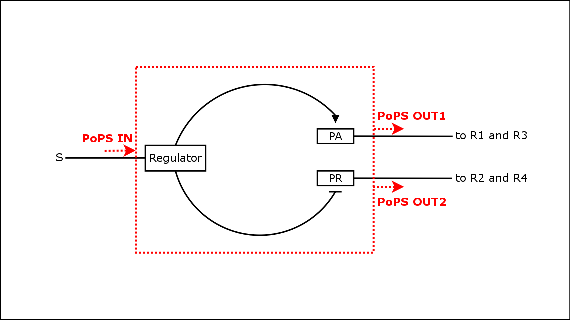
One of the outputs (PoPS OUT1) should be high and the other (PoPS OUT2) low when the PoPS IN is high and vice versa when PoPS IN is low.
