Synthetic Counter (iGem2005 ETH Zurich)
From 2006.igem.org
Christophe (Talk | contribs) (→Input Module) |
Christophe (Talk | contribs) (→Input Module) |
||
| Line 18: | Line 18: | ||
==Input Module== | ==Input Module== | ||
| - | |||
| - | |||
[[Image:InputModule_SingleScheme.gif|Parts-view of Input-module]] | [[Image:InputModule_SingleScheme.gif|Parts-view of Input-module]] | ||
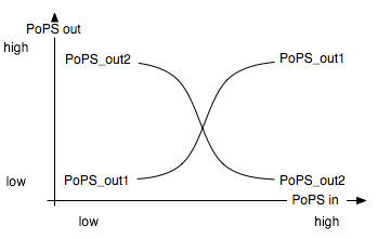
| - | The input module has 2 system boundaries. One of the outputs should be high and the other low when S is high and vice versa when S is low | + | The input module has 2 system boundaries. One of the outputs should be high and the other low when S is high and vice versa when S is low: |
[[Image:inputPops.png]] | [[Image:inputPops.png]] | ||
Revision as of 16:22, 15 October 2005
Abstract. We report here the design and implementation in vivo of a gene circuit that can count up to 4. In essence, it uses two toggle switches, each storing 1 bit, to keep track of the 4 states. The design of the counter is highly modular, with the hope that it can be included as a unit in larger circuits, and also combined with further counter instances to keep track of a much larger number of states, up to (2^(n+1)) with n units. To facilitate further developments and integration to other projects, the counter is available in form of BioBricks. Among many exciting applications, the availability of a counter enables the execution of sequential instructions, and paves the way for the execution of artifical programs inside living cells.
Contents |
Introduction
The past few years have seen the emergence of the field of synthetic biology, in which functional units are designed and built into cells to generate a particular behaviour, and ultimately to better understand Life's mechanisms. Previous efforts include the creation of gene circuits that generate oscillating behaviour (Elowitz00), toggle switch functionality (Atkinson03), artificial cell-cell communication (Bulter04) or pattern-forming behaviour (Basu2005). The present document describes the design and realization of a gene circuit that counts to 4.
Design of the Counter
The counter is a genetic circuit that has 1 input and 4 outputs. It uses the input signal to switch from one of the four output to the next. When the input signal is high, either output 1 or 3 is active, when it is low, output 2 or 4 is active. Thus, output 1 and 3 alternatively keep track of high input signal, while output 2 and 4 alternatively keep track of low input signals.
As depicted above, the counter is made of two parts, serially linked:
- the "Input" module, which splits the input into two opposite signals.
- the "NOR" module, which uses these two signals to sequencially switch through the outputs 1, 2, 3 and 4.
Note that all interfaces have flows described in Polymerase Per Second (PoPS), is explained in details on the [http://partsregistry.org/cgi/htdocs/AbstractionHierarchy/index.cgi abstraction hierarchy] of the MIT Registry of Parts.
Input Module
The input module has 2 system boundaries. One of the outputs should be high and the other low when S is high and vice versa when S is low:


