Tokyo Alliance: Design/Method
From 2006.igem.org
(Difference between revisions)
| Line 48: | Line 48: | ||
*System | *System | ||
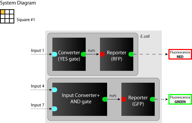
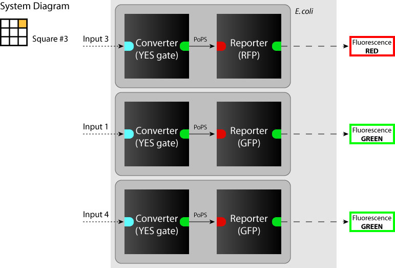
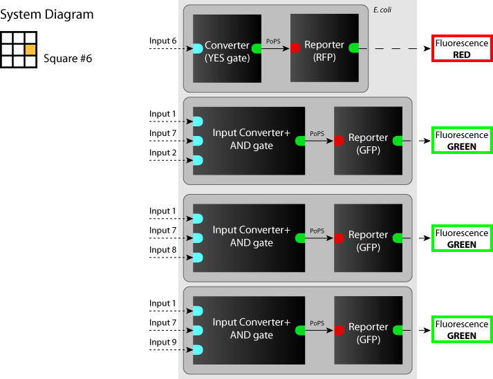
:[[Image:Tokyo_dev_sq_1.jpg|250px|System diagram: sq#1]] [[Image:Tokyo_dev_sq_3.jpg|250px|System diagram: sq#3]] [[Image:Tokyo_dev_sq_6.jpg|250px|System diagram: sq#6]] | :[[Image:Tokyo_dev_sq_1.jpg|250px|System diagram: sq#1]] [[Image:Tokyo_dev_sq_3.jpg|250px|System diagram: sq#3]] [[Image:Tokyo_dev_sq_6.jpg|250px|System diagram: sq#6]] | ||
| + | |||
| + | |||
| + | |||
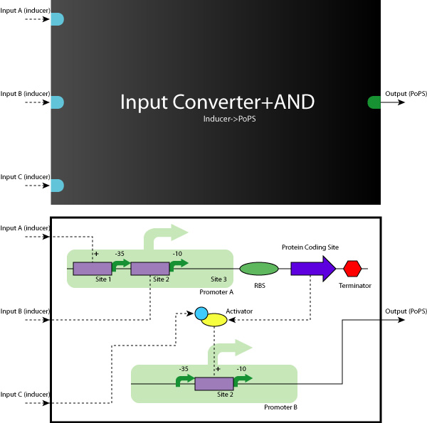
| + | *Device | ||
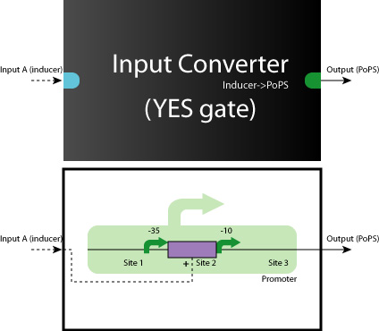
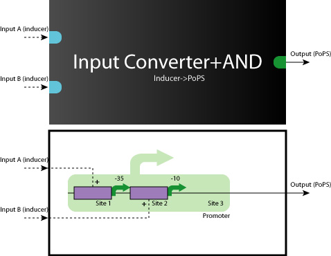
| + | :[[Image:Tokyo_dev_yes.jpg|250px|YES Gate]] [[Image:Tokyo_dev_and2.jpg|250px|AND Gate (2 inputs)]] | ||
| + | |||
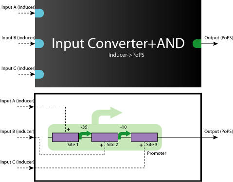
| + | :[[Image:Tokyo_dev_and3_1.jpg|250px|AND Gate (3 inputs) <1>]] [[Image:Tokyo_dev_and3_2.jpg|250px|AND Gate (3 inputs) <2>]] | ||
| + | |||
| Line 57: | Line 65: | ||
====working model==== | ====working model==== | ||
| - | *AND | + | *AND Gate (Repressor+Repressor) |
:[[Image:tokyo_workingmodel_1.jpg|500px|AND-AND gate (Repressor+Repressor)]] | :[[Image:tokyo_workingmodel_1.jpg|500px|AND-AND gate (Repressor+Repressor)]] | ||
| - | *AND | + | *AND Gate (Activator+Repressor) |
:[[Image:tokyo_workingmodel_2.jpg|500px|AND-AND gate (Activator+Repressor)]] | :[[Image:tokyo_workingmodel_2.jpg|500px|AND-AND gate (Activator+Repressor)]] | ||
Revision as of 14:39, 20 October 2006
Sorry, under construction...
Contents |
Systematic design concept/method
Abstraction Phase
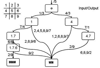
State Transition Diagram
- Combination of Noughts-and-Crosses
- 362,880(=9!)[patterns] (sum up all patterns)
- 255,168 (As a game)
- 26,830 (Eliminating symmetrical pairs)
We added the following rules to reduce the number of transition functions and inputs.
- 1st
- SYANAC goes to the center of the board. (sq#5)
- 2nd
- Human goes to the specific corner(sq#1) or the edge(sq#4) of the board.
- 3rd
- SYANAC must choose sq#3
Therefore, SYANAC's conbination patterns and inputs are as follows:
- SYANAC
- 25 combination patterns(Eliminating symmetrical pairs)
- 7 types of inputs
The State Transition Diagram shown right describes SYANAC's behavior based on this rule.
Logic Gates
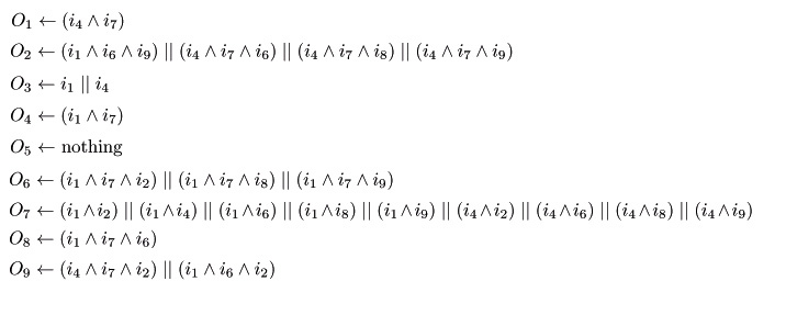
Here we show you the logic gates of each sq# according to the state transition.
Block Diagram (System/Device)
- System
- Device
Construction Phase
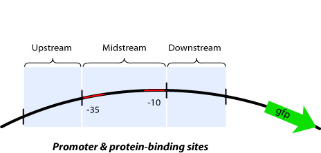
Up/Mid/Downstream
working model
- AND Gate (Repressor+Repressor)
- AND Gate (Activator+Repressor)
DNA Construction Procedure
- Midstream Parts Insertion
- [http://131.112.128.86/downloads/tokyo_mid_insertion.mov Midstream Parts Insertion Procedure (.mov)] (Requires QuickTime)

