Tokyo Alliance: Design/Method
From 2006.igem.org
| Line 115: | Line 115: | ||
</gallery> | </gallery> | ||
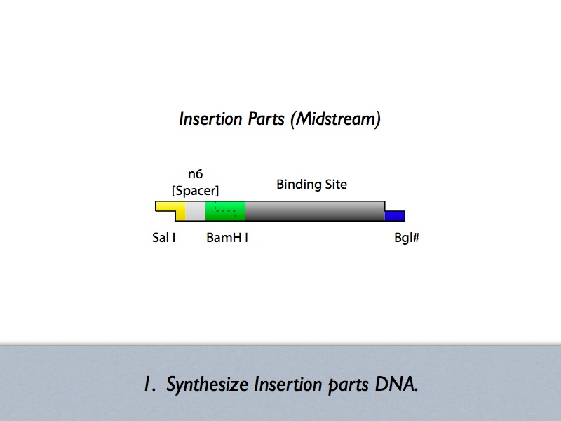
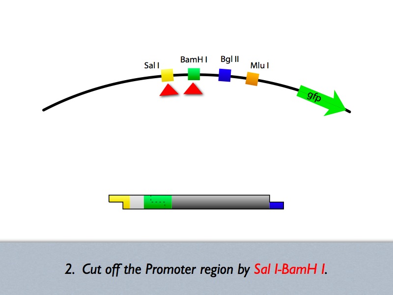
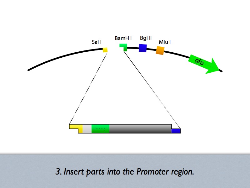
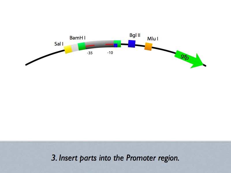
| - | + | Based on the iGEM construction method, divided three areas are generated new prefixes and suffixes. The prefixes are SalI and BglII sites. The suffixes are BamHI and MluI sites. Since, BamHI and BglII is compatible each other, we can insert several number of regulatory sequences purchased from oligo house into this area. For midstream part, a protein binding sequence is inserted between SalI and BamHI sites. While the vector has SalI and BamHI as prefixes, insert has SalI and BglII sites on its ends. After ligation, BamHI site of the vector disappear and another sequence can be inserted in front of this sequence. | |
Revision as of 20:30, 29 October 2006
Contents |
Systematic design concept/method
Abstraction Phase
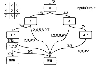
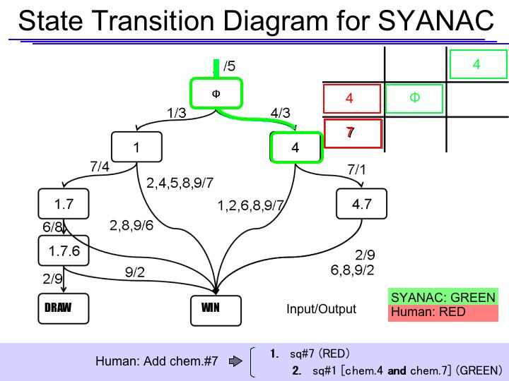
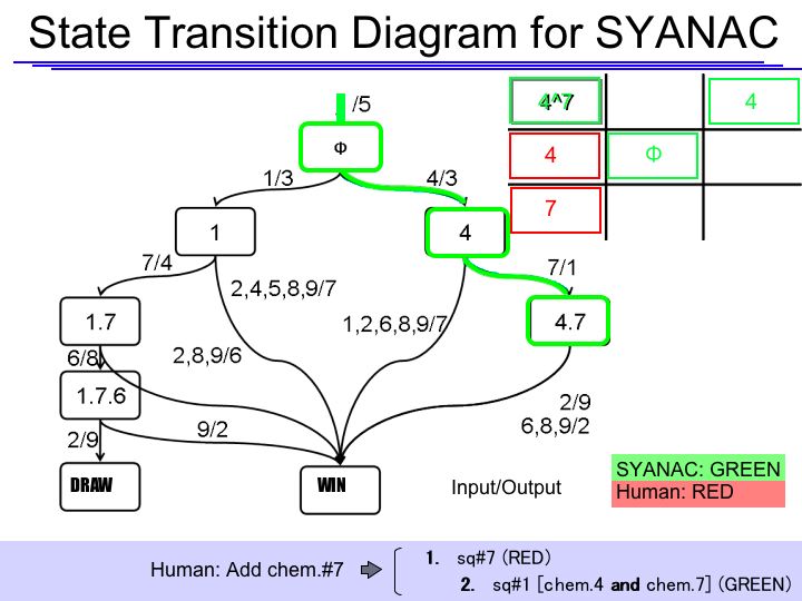
State Transition Diagram
- Combination of Noughts-and-Crosses
- 362,880(=9!)[patterns] (sum up all patterns)
- 255,168 (As a game)
- 26,830 (Eliminating symmetrical pairs)
We added the following rules to reduce the number of transition functions and inputs.
- 1st
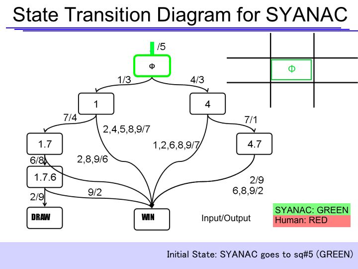
- SYANAC goes to the center of the board. (sq#5)
- 2nd
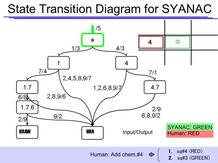
- Human goes to the specific corner(sq#1) or the edge(sq#4) of the board.
- 3rd
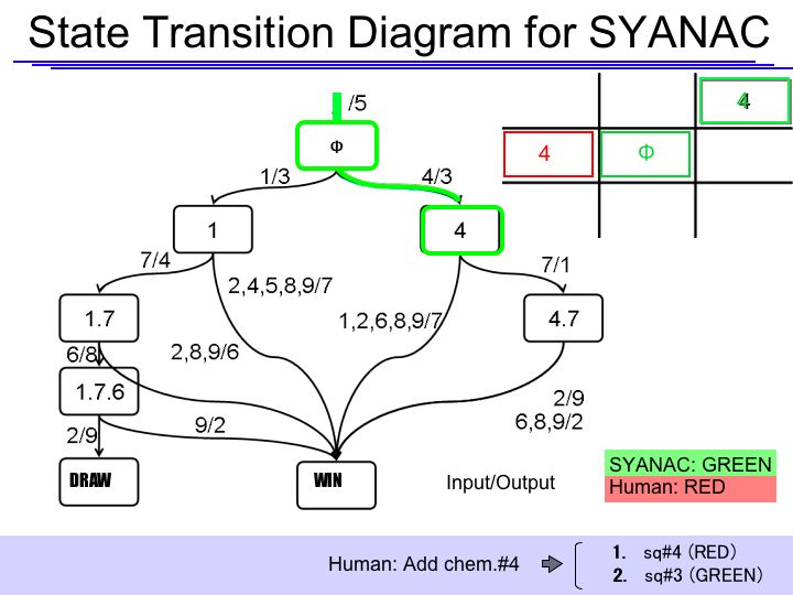
- SYANAC must choose sq#3
Therefore, SYANAC's conbination patterns and inputs are as follows:
- SYANAC
- 25 combination patterns(Eliminating symmetrical pairs)
- 7 types of inputs
The State Transition Diagram shown right describes SYANAC's behavior based on this rule.
State Transition Diagram Demonstration
if we test all of the SYANAC's move, we can draw this STATE TRANSITION DIAGRAM for SYANAC.
Logic Gates
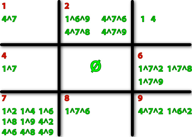
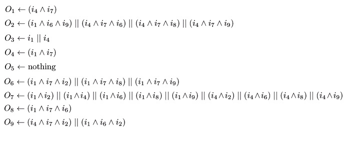
When we examined ALL of the patterns in the State Transition Diagram, we can decide logic gates we need in each square.
Here we show you the logic gates of each sq# according to the state transition.
Block Diagram (System/Device)
- System
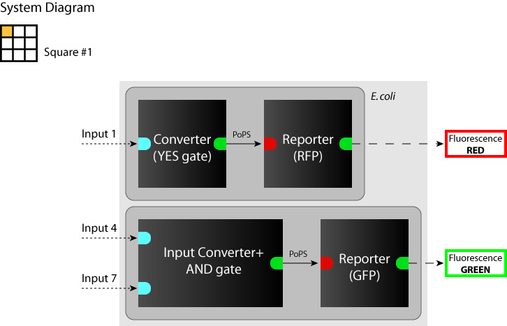
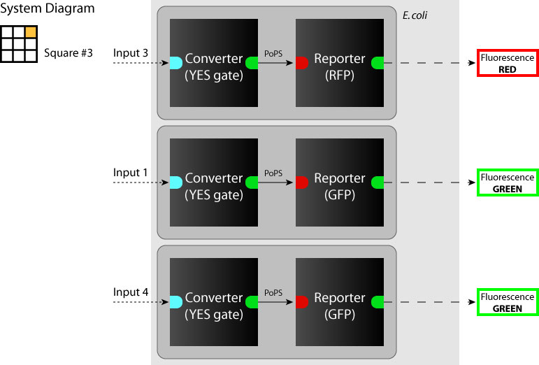
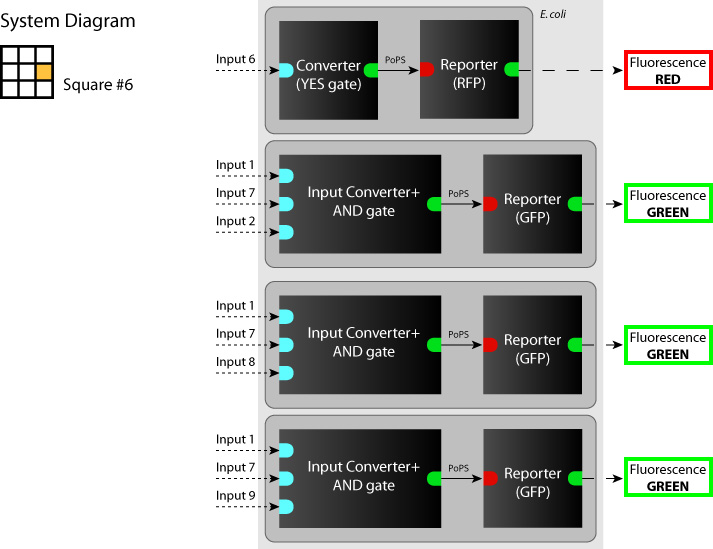
We determine each square as a system. (So we have to make 9 systems to make SYANAC.) We show some examples in figures below.
- Device
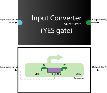
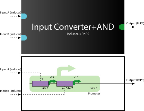
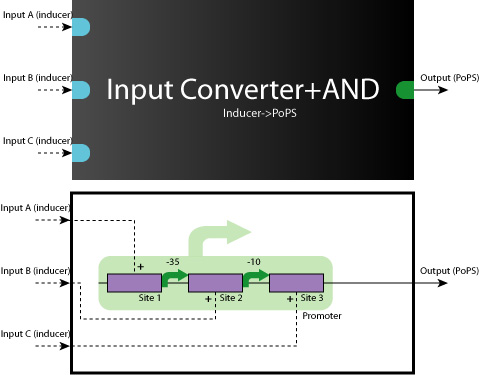
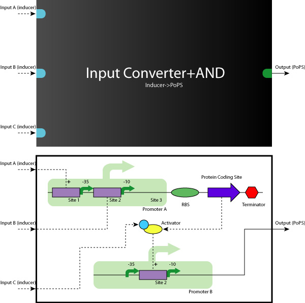
When we look at the Logic Gates of all 9 systems, they are all consisted of YES, AND, AND-AND Gates.
So, what we have to do is to construct these Logic Gates in a simple, systematic way.
Construction Phase
Up/Mid/Downstream
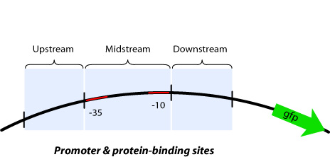
In order to implement logic gates, combination of several kinds of regulator binding sites is necessary. For this reason, separated three regions named upstream, midstream, and downstream as shown in figure is added new prefixes and suffixes in each end.
working model
Here we show you some typical working model examples of the Logic Gates.
- AND Gate (Repressor+Repressor)
- AND Gate (Activator+Repressor)
AND-AND Gates are also able to construct in the same way.
DNA Construction Procedure
- Midstream Parts Insertion
- [http://131.112.128.86/downloads/tokyo_mid_insertion.mov Midstream Parts Insertion Procedure (.mov)] (Requires QuickTime)
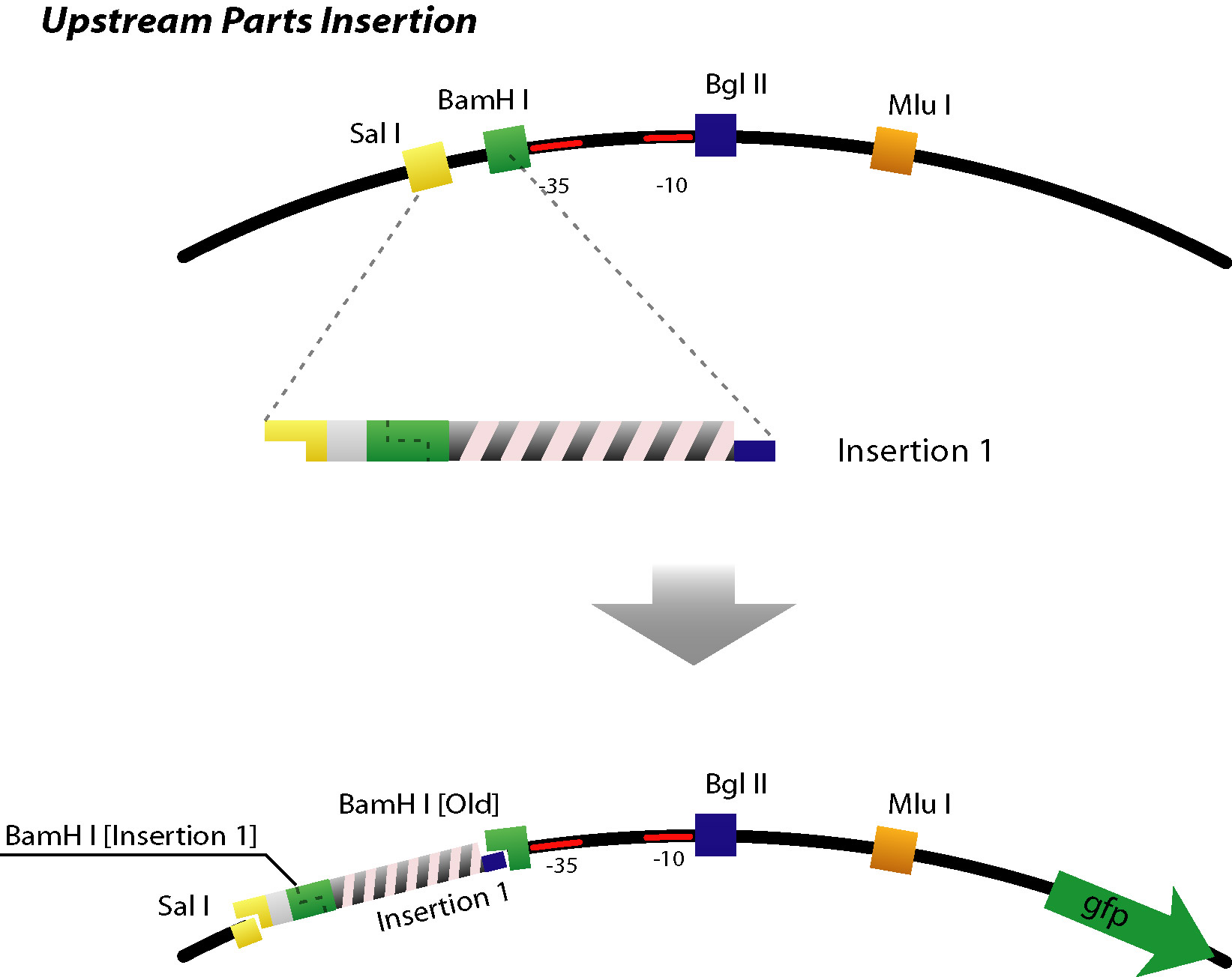
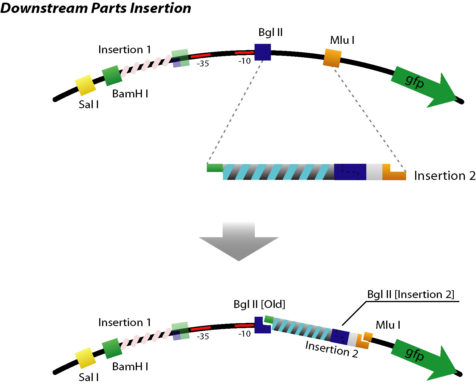
Based on the iGEM construction method, divided three areas are generated new prefixes and suffixes. The prefixes are SalI and BglII sites. The suffixes are BamHI and MluI sites. Since, BamHI and BglII is compatible each other, we can insert several number of regulatory sequences purchased from oligo house into this area. For midstream part, a protein binding sequence is inserted between SalI and BamHI sites. While the vector has SalI and BamHI as prefixes, insert has SalI and BglII sites on its ends. After ligation, BamHI site of the vector disappear and another sequence can be inserted in front of this sequence.
- Up/Downstream Parts Insertion
- Next parts can be inserted with the same procedure. (Up/Downstream Insertion Parts)

