ETH Zurich 2006
From 2006.igem.org
Contents |
CHAOS CLONING CLUB (CCC)
News
- 2005.10.25 Now we know that Blue Heron will not be able to deliver in time.
- 2005.10.24 We had a very intensive meeting on the overall concept and the documentation of the project. This page will change a lot in the coming days.
- 2005.10.23 One month after ordering, the sequences are still not ready. That means it is unlikely for us to complete the 4-State Device before the jamboree unless we find some alternative solutions (and have quite a bit of luck). See message from blue herons web page:
IMPORTANT NOTE: Despite Blue Heron Bio's capacity expansion, record order volume has created larger than anticipated queuing, which has increased delivery times for some orders. We are reviewing Estimated Ship Dates regularly to provide you with our best estimate of when your order will ship. We are working hard to deliver your orders as quickly as possible, and we are implementing new capacity management systems to avoid this problem in the future. If you have any questions or concerns please call our Customer Service.
- 2005.10.18 The parts for the actual Event Processing Device are ready, thanks to the hard work of Giorgia, Hervé, and Maartje (not all test/debugging parts though)
- 2005.10.07 Message from Blue Heron: Sequences for NOR are synthesized and will be verified and assembled next week.
- 2005.09.23 Sequences for 4-State Device ordered from Blue Heron
Organisation
People
Students
| Simon Barkow | Christophe Dessimoz | Zlatko Franjcic |
| Dominic Frutiger | Robin Künzler | Urs A. Müller |
| Jonas Nart | Kristian Nolde | Alexander Roth |
| Tamara Ulrich | Giorgia Valsesia | Herve Vanderschuren |
Supervisors
| Jörg Stelling | Sven Panke | Eckart Zitzler |
Advisors
| Uwe Sauer | Martin Fussenegger | Andreas Hierlemann |
| Kay-Uwe Kirstein | Ruedi Aebersold |
Timeline
Tasks
=Abstract= The project of the ETH Zurich team consists of the design and [http://en.wikipedia.org/wiki/In_vivo in vivo] implementation of a gene circuit that can count to 2. In essence, the counter uses two toggle switches, each storing 1 bit, to keep track of the 4 internal states. The design of the counter is highly modular, with the hope that it can be included as a unit in larger circuits, and also combined with further counter instances to keep track of a much larger number of states, up to 2^n with n units. To facilitate further developments and integration to other projects, the parts of the counter are available in form of [http://parts2.mit.edu/ BioBricks]. Among many exciting applications, the availability of a counter enables the execution of sequential instructions, and therfore paves the way for the execution of artificial programs inside living cells.
Introduction
The past few years have seen the emergence of the field of Synthetic Biology, in which functional units are designed and built into living cells to generate a particular behaviour, and ultimately to better understand Life's mechanisms. Previous efforts include the creation of gene circuits that generate oscillating behaviour ([http://www.ncbi.nlm.nih.gov/entrez/query.fcgi?cmd=Retrieve&db=PubMed&dopt=Citation&list_uids=10659856 Elowitz00]), toggle switch functionality ([http://www.ncbi.nlm.nih.gov/entrez/query.fcgi?cmd=Retrieve&db=PubMed&dopt=Citation&list_uids=12787501 Atkinson03]), artificial cell-cell communication ([http://www.ncbi.nlm.nih.gov/entrez/query.fcgi?cmd=Retrieve&db=PubMed&dopt=Citation&list_uids=14983004 Bulter04]) or pattern-forming behaviour ([http://www.ncbi.nlm.nih.gov/entrez/query.fcgi?cmd=Retrieve&db=PubMed&dopt=Citation&list_uids=15858574 Basu2005]). In the framework of the [http://parts2.mit.edu/wiki/index.php iGEM2005 summer competition] we have evaluated several potential novel ideas, and decided to realize a gene circuit that counts external events to 2 - with the possibility to be extended to more complex systems. The present document describes the design and implementation of the device.
Concept
The counter is a finite state machine implemented as a genetic circuit. It has 4 internal states R1 to R4. The transition between these states is induced by an external stimulus with values 0 and 1 - denoting whether it is absent or present, respectively. Repeated stimulus will lead to successive transitions and finally to repeated cycling through those 4 states.
Each time the state R4 is reached, an output signal is generated. This leads to a counting behavior where every second occurence of 1 (high signal) is indicated by the output signal.
Further information on the state machine
System Implementation
System Architecture
Below you find an illustration of the counter system according to the [http://partsregistry.org/cgi/htdocs/AbstractionHierarchy/index.cgi abstraction hierarchy] of the MIT Registry of Parts. Also note that all interfaces have flows described in Polymerase Per Second (PoPS).
System Level
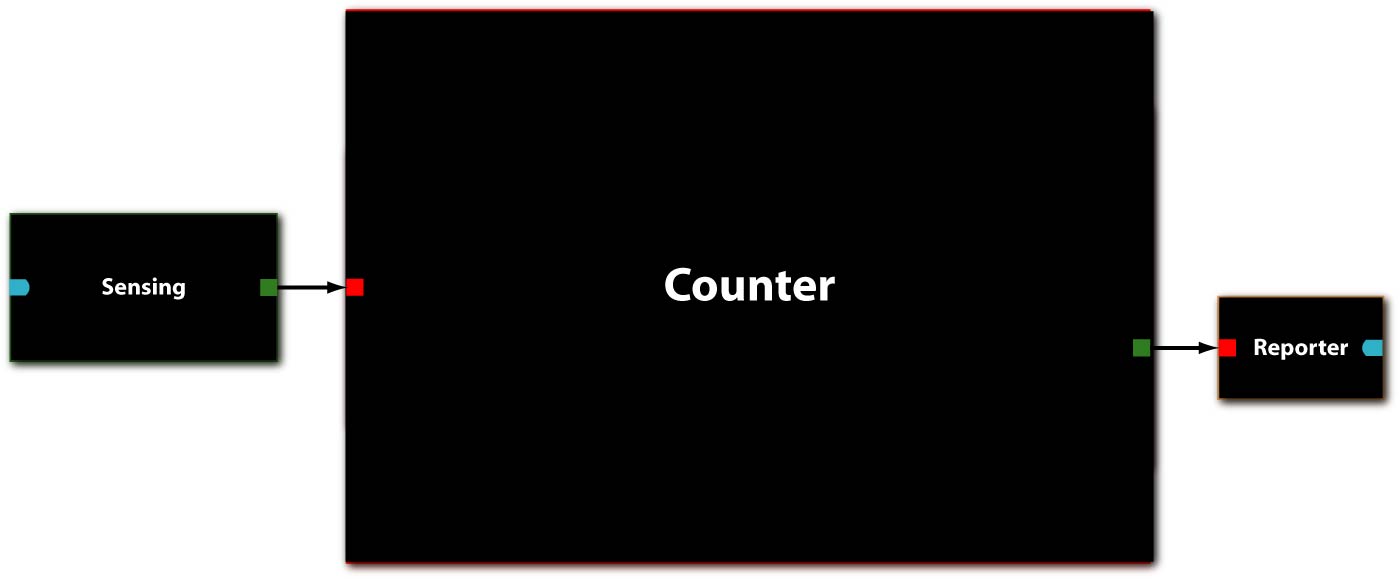
In [Fig 1] you can see the system abstraction level of our Counter. It takes one PoPS-encoded signal as an input from a sensing device and outputs a signal in form of high PoPS at every other detected event to a reporting device.
Device Level
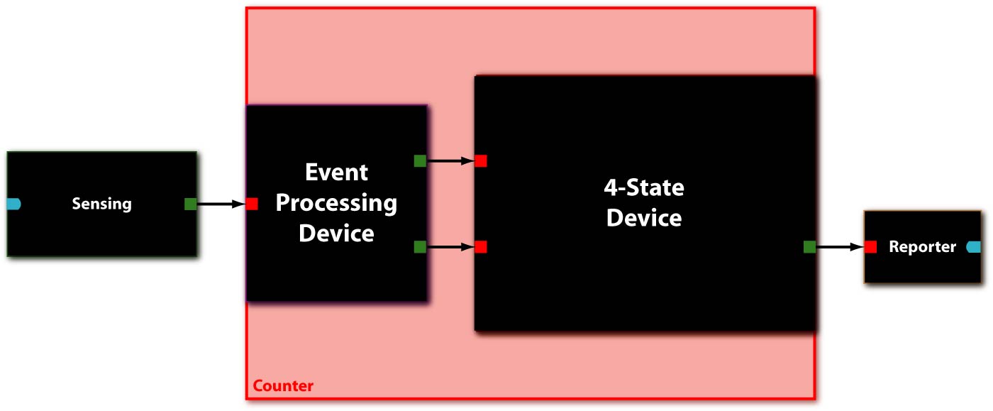
The Counter system itself consists of two devices [Fig 2], serially linked:
- The Event Processing Device (EPD), which splits the input into two outputs: one feed through and one inverted signal with similar delays - which serve in turn as inputs for the 4-State Device.
- The 4-State Device (4SD) module, which uses these two signals to sequentially switch through the states R1, R2, R3 and R4.
For this prototype we have two additional devices to detect a test signal and to produce a reporter, respectively:
- The sensing device to detect internal events and convert it to an input signal for the Event Processing Device
- The reporting device to make the output of the 4-State Device observable.
Because of the PoPS interface at the system boundaries, the input to the EPD can be of any nature as long as an adequate promoter is available for the sensing device (e.g. heat-shock using a sigma32 promoter, IPTG using a LacI promoter, AHL using quorum sensing promoters...). The same of course applies also to the output, i.e. the reporting device is independent of the Counter system.
Parts Level
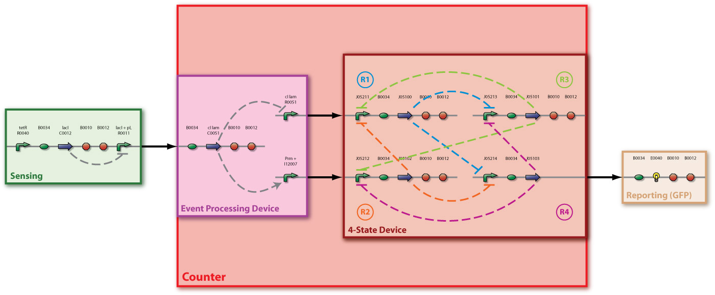
[Fig 3] shows the device level and the detailed parts level (with [http://parts2.mit.edu/r/parts/htdocs/AbstractionHierarchy/index.cgi| BioBrick] symbols) and detailed protein interaction.
Devices
Event Processing Device (EPD)
Basic Functionality
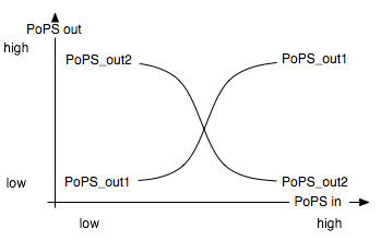
The Event Processing Device splits the input induced by an external event into two signals: one is basically fed through while the other is inverted. The device is best described through its system boundaries: in absence of an input signal the system is in its ground state and one of its two outputs is high while the other is low. The outputs are inverted as soon as there is an input signal S present [Fig EPD.1]. Both output signals then serve as input signals for the 4-State Device and it is thus necessary that they have approximately the same delay.
Biological Implementation
Biologically, a system has to be found and/or designed that provides two opposing outputs controlled by some regulator protein which in turn depends on a sensor system which ideally can be exchanged. The unidirectional λ-phage system from the [http://parts2.mit.edu/| MIT parts registry] seemed to be the most promising and feasable solution to this regulator problem.
As an input system to the EPD we chose the well known lac-system which can be triggered by IPTG to simulate an external event. This system is certainly not perfect, but well suited for a first prototype implementation within the framework of iGEM 2005.
Detailed Documentation
For more details, please consult the main page for the Event Processing Device.
4-State Device (4SD)
Basic Functionality
The 4-State Device uses two inputs to sequentially switch through four states. At every second occurence of a high main input signal, the fourth state is reached. Note that this behaviour can be observed abstractly in the concept section.
To achieve this behaviour, we use the idea of an electronic circuit with four NOR gates, each having three input signals. These gates are connected in such a way, that at any time one of them has high and all the others have low output. We define the gate with high output as the active state. Each time the main input signal rises or drops, the active state ist changed: The next gate in the sequence becomes active.
Biological Implementation
To implement the NOR gates biologically, many different repressors are needed. We use Zinc Finger proteins (ZFP) as repressors. This class of proteins binds to specific base pairs sequence on the DNA. Many protein-DNA interactions for ZF domains and triplet of base pairs have been described, therefore making it possible to design artificial transcription factors by combining ZF domains in a modular fashion. The idea is to use a ZFP as a repressor by putting a binding site for a ZFP upstream of the coding DNA sequence and thereby preventing RNA polymerase from transcribing this coding sequence.
Detailed Documentation
More details can be found in the dedicated 4-State Device page.
Mathematical Modeling
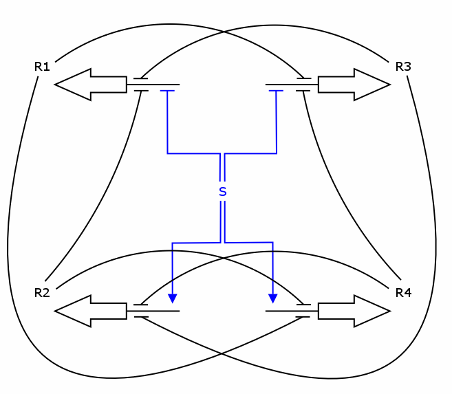
The simulation was performed through a deterministic model using ordinary differential equations (ODEs), as this approach is commonly used in modeling gene networks. Recall the counter architecture in [Figure Simulation 1].
R1 to R4 are the zincfingers that are expressed. S is the input of the counter. Note that the work of the Event Processing Device is symbolized by the dual effect of S, once as an activator and once as a repressor. Zincfingers R1 and R3 have Pr as a promoter, R2 and R4 have Prm as a promoter. See Event_Processing_Device for more details.
Note: This figure needs to be updated!
The 4 corresponding differential equations are:
dR1/dt = k_syn_R1 * rep(S) * rep(R2) * rep(R3)  -  k_deg_R1 * R1
dR2/dt = k_syn_R2 * act(S) * rep(R3) * rep(R4)  -  k_deg_R2 * R2
dR3/dt = k_syn_R3 * rep(S) * rep(R1) * rep(R4)  -  k_deg_R3 * R3
dR4/dt = k_syn_R4 * act(S) * rep(R1) * rep(R2)  -  k_deg_R4 * R4
         \_________________ _________________/  \_______ _______/
                           V                            V
                    synthesis rate               degradation rate

 where   act(A) = (A/K_act)^n / (1+(A/K_act)^n)
   and   rep(R) = 1 / (1+(R/K_rep)^n)

 K are affinity constants, while k are kinetic constants.
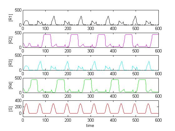
Solving the system in Matlab using reasonable affinity and kinetic constants, the result can look as in [Figure Simulation 2].
As expected, [R4] follows every second peak of [S].
By exploring the parameter space and performing Sensitivity Analysis, the following conclusions could be drawn:
- Changes in the affinity/cooperativity of the input signal S affect the system more strongly than changes in the affinity/cooperativity of the zincfingers.
- The affinities of the zincfingers/input signal S are more sensitive than the cooperativities.
- The maximum procuction rate and the degradation rate of the zincfingers are the most sensitive parameters. The maximum expression rate is a bit more sensitive, but they are quite close together.
- The affinity constants R1..R4 should be as symmetrical as possible, in particular the couples R1,R3 and R2,R4. A difference in the affinity constant up to an order of magnitude appears tolerable.
- ...
More details of the simulation work are reported on the page Mathematical_Modeling.
Results
We have ongoing experiments and the documentation is not up to date / well structured. In the meantime, please refer to the Experiments page.
Discussion
Outlook
As already mentioned in the introduction the field of Synthetic Biology is still very young but shows a lot of potential. At this stage every new development can have huge effects on the general focusing of the field. During our project we came to the point where we had to decide whether we want to go for a cool and fancy behaviour or for a part that can be reused in the future for many other things (see the previous ideas). The result described in detail in the above sections show obviously that we went for the ladder. People who hear about Synthetic Biology for the first time by reading about our project might think: “Why should a bacterium be able to count to two?” A good question. In order to give an answer and also a feeling about the mightiness of our approach to the reader, we want to list a few of our ideas in the following:
One of the first things that comes to one’s mind is to add further 4SDs in series. This way you could not only count to 2 but to 2^n, where n is the number of 4SDs. You only have to change the zincfingerproteins of each 4SD in order to avoid interactions (for 3 fingers there are already about 250’000 possible combinations). With 64 of these 4SDs we would already have the instruction length of the latest computers.
But our counter can’t only be seen in the common sense. You can also use it to provide a certain sequence of actions. By adding to carefully selected states an extra DNA strand coding a protein one could control a complicated sequence by only giving input signals at the event processing device. The network of 4SDs would do the rest. Such a network could also have parallel parts as the output of one state could be used as input of two or more other 4SDs.
As in the Registry of Standard Biological Parts the inputs and outputs of the parts are defined by PoPS any imaginable input could be used for the counter (you only need to find a proper promoter). E.g. a protein which is typical for a certain state in the cell division cycle could be used to count the number of cell divisions. With a periodical input a clock is also achievable.
Furthermore the different parts of the counter could be reused too: the 4SD (or just parts of it) for example as a simple NOR-gate or J-K-flip-flop.
Besides all these practical applications any engineer would approve that a counter is a crucial part for a finite state machine. Therefore this counter could be a part of the heart of a future biological computer. Such a computer can’t work as fast as common processors made of silicon of course. But as in a single drop millions of bacteria can exist, this drop could have the power of a huge computer network.
Appendix
References
atkinson03, basu05, bates05, Beerli00 (Linker), Beerli02, Beerli98, bulter04, cho04a-sensitivity, Chou et al. 1998, Dreier01 (ANN-paper), Dreier05 (CNN-paper), goryachev05, Greisman97, Isalan01, keiler01, Klug05 (Minireview), Lai04, Mani05, miller01, Newman03 (Leucine Zippers), Park et al. 2005 (Activation of transcription), römling02, ross91, Segal03, Segal99 (GNN-paper), sudesh00, suetsugu03, sutherland01, Yang95 (Kinetics!!), you04, zogaj01
Glossary
Previous Ideas
This is the brainstorming and previous ideas section. In this section you will find other projects that had been pursued, as well as random ideas without too much consideration of feasibility, etc.

